Ao h m, Selection procedure – Thermal Transfer Systems AOVHM Series User Manual
Page 4
AO
H
M
www.thermaltransfer.com
262.554.8330
47
A
IR C
O
O
L
E
D
A
OHM
/A
OV
HM
Selection Procedure
Performance Curves are based on 50 SSU oil entering the cooler 50°F higher
than the ambient air temperature used for cooling. This is referred to as a
50°F E.T.D.
Step 1
Determine the Heat Load. Heat load may be expressed as either
horsepower or BTU/Hr. To convert horsepower to BTU/Hr.:
BTU/HR = Horsepower x 2545
Step 2
Determine Entering Temperature Difference. The entering oil
temperature is generally the maximum desired oil temperature.
Entering oil temperature – Ambient air temperature = E.T.D.
Step 3
Determine the Corrected Heat Dissipation to use the curves.
Corrected Heat Dissipation =
BTU/HR heat load x 50°F
E.T.D.
x viscosity correction A.
Step 4
Enter curves at oil flow through cooler and curve heat dissipation.
Any curve above the intersecting point will work.
NOTE: Performance curves shown are for 1 and 2 pass
configuration.
EXAMPLE: 35 - 2 is AOHM or AOVHM - 35
Step 5
Determine Oil Pressure Drop from Curves:
l
= 5 PSI; n = 10 PSI; s = 20 PSI. Multiply pressure drop from
curve by correction factor B found in oil viscosity correction curve.
Desired Reservoir Temperature
Oil Temperature: Oil coolers can be selected using entering or leaving oil
temperatures.
Off-Line Recirculation Cooling Loop: Desired reservoir temperature is
the oil temperature entering the cooler.
Return Line Cooling: Desired reservoir temperature is the oil temperature
leaving the cooler. In this case, the oil temperature change must be
determined so that the actual oil entering temperature can be found.
Calculate the oil temperature change (oil
#
T) with this formula:
Oil
#
T = (BTU’s/Hr.) / (GPM Oil Flow x 210).
To calculate the oil entering temperature to the cooler, use this formula:
Oil Entering Temp. = Oil Leaving Temp + Oil
#
T.
Oil Pressure Drop: Most systems can tolerate a pressure drop through the
heat exchanger of 20 to 30 PSI. Excessive pressure drop should be avoided.
Care should be taken to limit pressure drop to 5 PSI or less for case drain
applications where high back pressure may damage the pump shaft seals.
Oil Temperature
Typical operating temperature ranges are:
Hydraulic Motor Oil
120°F - 180°F
Hydrostatic Drive Oil
160°F - 180°F
Engine Lube Oil
180°F - 200°F
Automatic Transmission Fluid
200°F - 300°F
Hydraulic Motor
MODEL
SIZE
MAXIMUM FAN SPEED
(RPM)
68
68
69
70
72
75
76
78
1725
5
10
15
20
25
30
35
40
AOHM
AOVHM
1140
3450
1725
AOHM
AOVHM
AOHM
AOVHM
1.6
1.1
3.3
3.4
5.2
300
400
900
300
500
1000
OIL FLOW REQUIRED
(GPM)
MIN. OPERATING
PRESSURE (PSI)
AOHM
AOVHM
SOUND dB(A)*
85
85
91
91
81
84
89
91
.22
MOTOR (in
3
/rev.)
DISPLACEMENT
AOHM
AOVHM
.22
.45
.70
AOHM
AOVHM
CFM
465
669
956
1460
2160
2990
4370
5450
780
1110
1590
2168
3000
4095
5921
9609
Notes: Maximum pressure is 2000 psi. Stated minimum operating pressure is at inlet port of motor. 1000 psi allowable back pressure.
*Catalog db(A) sound levels are at seven (7) feet. dB(A) sound levels increase by six (6) dB(A) for halving this distance and decrease by (6) dB(A) for doubling this distance.
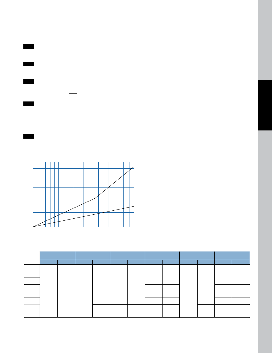
OIL VISCOSITY CORRECTION MULTIPLIERS
A
B
VI
SC
OS
IT
Y
CO
RR
EC
TI
ON
OIL VISCOSITY SSU
6
5
4
3
2.5
2
1.5
1
50 60 65 70 75 80 90 100 200 300 400 500 600 700 800