Ao f, Dimensions – Thermal Transfer Systems AOF Series User Manual
Page 2
AO
F
www.thermaltransfer.com
262.554.8330
17
A
IR C
O
O
L
E
D
AO
F
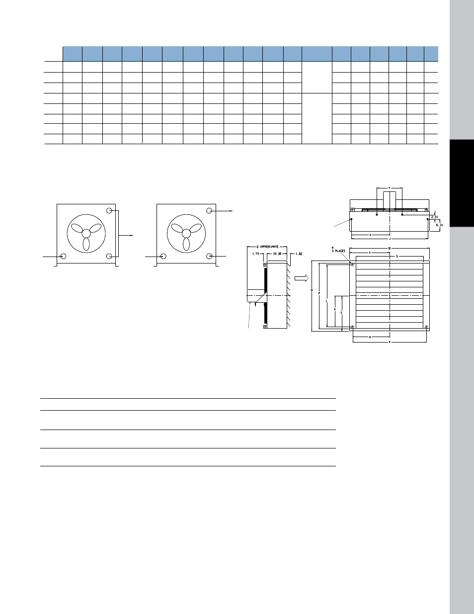
Dimensions
Model
A
B
C
D
E
F
G
H
J
K
L
N
P
Q
R
S
T
M
NPT
M
SAE
AOF-5 7.40 14.81 5.90 11.81 17.50 9.19
8.31
6.47 12.94 3.78
7.69
1”
#16 SAE 5.84 11.69 10.06 1.09 3.92
—
AOF-10 9.50 19.00 6.56 13.12 17.00 10.50 12.50 8.56 17.12 4.44
8.88
1”
1-5/16-12UN-2B
7.94 15.88 14.38 1.09 3.92
—
AOF-15 10.19 20.38 7.87 15.75 17.62 13.12 13.88 9.25 18.50 5.75 11.50
1”
Thread
8.62 17.25 15.62 1.09 3.92
—
AOF-20 11.91 23.81 9.19 18.38 19.62 15.75 17.91 10.90 21.81 7.00 14.00 1-1/4”
10.28 20.56 18.62 1.09 3.92
—
AOF-25 13.34 26.68 11.81 23.62 20.68 21.00 20.19 12.40 24.81 9.62 19.25 1-1/4” #20 SAE 11.78 23.56 21.62 1.09 3.92 —
AOF-30 15.81 31.62 13.78 27.56 20.12 24.94 25.12 14.87 29.75 11.59 23.19 1-1/4”
1-5/8-12UN-2B
14.25 28.50 26.62 1.09 3.92 11.00
AOF-35 16.90 33.81 15.09 30.19 21.25 27.56 27.31 15.97 31.94 12.90 25.81 1-1/4” Thread 15.34 30.69 28.88 1.09 3.94 11.00
AOF-40 20.81 41.62 18.37 36.75 20.31 34.12 35.12 19.87 39.75 16.19 32.38 1-1/4”
19.25 38.50 37.00 1.18 3.87 13.25
Fan Rotation Clockwise/Facing Motor Shaft
Installation Piping Diagram
*See dimension chart for NPT or optional internal SAE connection size.
NOTE: All dimensions in inches.
One Oil Pass
Two Oil Passes
1/2-13 UNC-28
4 Places
8 Places on
AO-30, 35 & 40
(Top & Bottom)
AIR
FLOW
NOTE: MOTOR MOUNTING BRACKET ON
AO-5 & AO-10 IS ROTATED 90°
Oil
IN
Oil
OUT
Oil
IN
Air
Cap
Oil
OUT
Oil
IN
Oil
OUT
Oil
IN
Air
Cap
Oil
OUT
Lubrication Notes
Caution: Do not over oil or over grease. Ball bearings – No grease needed at start up. Grease as follows:
5,000 Hours/Year
5 Year Grease Interval
Continuous
2 Years
Normal Applications
Seasonal Service
1 Year
Motor is idle for 6 months or more
Continuous
6 Months
High ambients, dirty or moist locations, high vibration