Uc /uc v, Dimensions – Thermal Transfer Systems UCV Series User Manual
Page 5
UC
/UC
V
262.554.8330
www.thermaltransfer.com
122
W
A
T
E
R C
O
O
L
E
D
UC
/UC
V
Dimensions
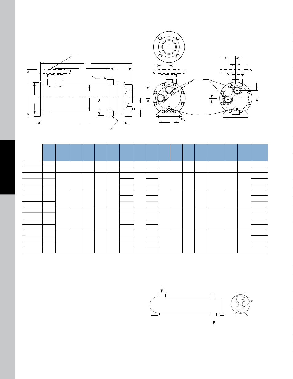
UCV Four Pass
*150# ASME/ANSI Flange. NOTE: We reserve the right to make reasonable design changes without notice. Consult factory. All dimensions are inches.
R
P
R
R
E
H
A
G
N Inlet
3/4" NPT
Vent
F
C
B
J
N Outlet
K
M
L
(2 EACH END)
R
.50
.50
D
MODEL
612
624
812
824
836
1012
1024
1036
1218
1224
1236
1248
1724
1736
1748
1760
A
17.20
29.20
19.47
31.47
43.47
19.50
31.50
43.50
26.22
32.22
44.22
56.22
34.69
46.69
58.69
70.69
FT
SURFACE
AREA
2.4
4.7
4.0
7.9
11.9
7.4
14.5
21.5
15.3
21.1
31.3
41.6
47.7
70.1
92.5
114.8
G
11.00
23.00
12.38
24.38
36.38
11.50
23.50
35.50
17.38
23.38
35.38
47.38
23.00
35.00
47.00
59.00
J
17.66
29.66
19.65
31.65
43.65
19.95
31.95
43.95
26.12
32.12
44.12
56.12
34.27
46.27
58.27
70.27
B
DIA
4.50
6.00
6.75
7.75
10.50
E
2.75
3.50
4.00
4.50
5.75
D
2.62
3.15
3.70
4.22
5.58
F
DIA
3.25
4.25
5.25
6.25
8.62
H
3.98
4.60
5.18
5.38
7.31
L
.44
DIA
.44
DIA
.50
x .75
SLOT
.50
x .75
SLOT
.62
x .88
SLOT
N
INLET
1.25
1.50
2.00
3.00*
4.00*
K
3.25
3.50
4.00
5.00
7.00
R
1.00
1.25
1.69
2.00
2.50
N
OUTLET
.75
.75
1.00
1.00
1.50
P
NPT
.75
.75
1.00
1.50
2.00
M
NPT
(2)
.38
(2)
.38
(2)
.38
(2)
.38
(2)
.38
C
5.25
6.75
7.77
10.38
13.00
2
COOLING
WATER
VENT
HOT FLUID OUT
HOT FLUID IN
Piping Hook-up
UCV Applications
U-Tube Heat Exchangers allow the shell and tube bundle to expand
and contract independently with temperature fluctuation. This reduces
temperature dependent stresses so they are ideal in applications with
large temperature differentials. Some typical examples for UCV units
include steam to liquid heaters, vapor condensers, and steam condensers.
The removable bundle design allows for easier cleaning of the shell side
cavity when the bundle is removed.
Specific applications may have different piping arrangements.
Consult factory for assistance.
All models except
UCV-1700 Series
UCV-1700 Series