13 wall mounting the spectrum plus, Telephone, Desk mounting – Telematrix SP200 User Manual
Page 13
13
Wall Mounting the Spectrum PLUS
TM
Telephone
To install the wedge for desk mounting, be sure the lock mechanism is positioned to the left
clear of the locking arm. Place the wedge in the slots, wide end toward top o f phone base
unit, and slide the wedge upward into position. Lock the wedge into place.
Desk Mounting
2. T he S pectrum P LUS
TM
h as pr ovisions f or a
mounting wedge that must be correctly positioned.
This wedge allows the telephone to be viewed at a
correct an gle w hen th e ph one is w all mou nted.
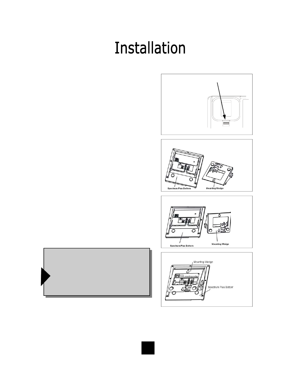
Remove the wedge from the phone base (figure 2).
3. Secure the line cord, coil cord and any wiring in
place prior to installing the wall mount wedge. The
wall m ount b ase has e xtra l arge wi ring c hannels
and strain relief poles for containing the wires in a
neat an d o rderly w ay. Wr ap t he wi res aro und t he
strain re lief po les an d t hen se cure t he wi res
through the channel.
4. To wall mount, place the narrow edge at the top
edge of th e ph one base and slide th e w edge u p-
ward into place (figure 3).
5. Lock the wall mount into pos ition by s liding the
locking button to the right (figure 4).
Note: A 6-inch line cord is provided for when
the telephone is to be wall mounted. Connect
one end of the line cord to the phone jack and
the other end to the wall jack. Be sure to con-
nect the power cord and line cords before plac-
ing mounting wedge on the bottom base. An
optional coaxial power supply can be used in
place of the supplied power supply. See your
local distributor for information.
!
figure 2
Replace Mounting Wedge
figure3
Replace Mounting Wedge
figure 4
Lock Mounting Wedge
The S pectrum P LUS
TM
was de
signed t o b e
conveniently w all moun ted w ithout r equiring
additional hardware.
Follow these easy steps:
1.The handset retaining clip must be in th e correct
position to s ecure th e ha ndset in to th e h andset
cradle. E ngage th e c lip with y our f ingers a nd p ull
the clip forward (towards you), rotate th e clip 180º
and s nap th e c lip ba ck in to pla ce ( figure 1) . Th e
retaining clip cannot be removed.
RETAINER CLIP
figure 1
1. U N S NA P
2. R O TAT E 1 80 .
3. SN AP I NT O P LA C E.
NOTE: CLIP IS
1.LIFT CLIP OUT WITH
FINGERS. IT CANNOT BE
REMOVED BECAUSE IT
IS SPRING LOADED.
2. ROTATE THE
CLIP 180
0
AND
IT WILL SMAP
BACK INTO THE OPPO-
SITE POSITION. AN