Operating instructions, Lighting procedure, Optional wall thermostat – Regency Excalibur EX-U31 Medium Gas Insert User Manual
Page 24: Optional remote control, Final check, 820 s.i.t. valve description
24
Regency U31-3 Gas Fireplace Insert
24
OPERATING INSTRUCTIONS
OPERATING
INSTRUCTIONS
Before operating this appliance, proceed through
the following check list.
1) Read and understand these Instructions before
operating this appliance.
2) Check to see that all wiring is correct and
enclosed to prevent possible shock.
3) Check to ensure there are no gas leaks.
4) Make sure the glass door is in place. Never
operate the appliance with the door glass
removed.
5) Verify that all venting and the cap is unob-
structed.
6) Verify log placement. If the pilot cannot be seen
when lighting the unit - the logs or the embers
have been incorrectly positioned.
7) The unit should never be turned off and on
again without a minimum of a 60 second wait.
8) When lighting the appliance, the inside of the
glass may fog up. This will burn off after a few
minutes of operation.
LIGHTING
PROCEDURE
IMPORTANT: Gas cock knob cannot be turned
from "PILOT" to "OFF" unless it is partially
depressed.
1) Open the bottom louver assembly
OPTIONAL WALL
THERMOSTAT
A wall thermostat may be installed if desired. Con-
nect the wires as per the wiring diagrams. Note
that the wires are connected to the "TH" on the
gas valve. Use table on page 14 to determine the
maximum wire length:
Note: Preferable if the thermostat is installed
on an interior wall.
FPI offers an optional programmable thermostat
but any 250-750 millivolt rated non-anticipator
type thermostat that is CSA, ULC or UL approved
may be used.
OPTIONAL REMOTE
CONTROL
Use the FPI Remote Control Kit approved for
this unit. Use of other systems may void your
warranty.
The remote control kit comes with a hand held
transmitter, a receiver and a wall mounting plate.
1) Choose a convenient location on the wall
to install the receiver and the receptacle
box (protection from extreme heat is very
important). Run wires from the fi replace to
that location, use Thermostat Wire Table.
2) Connect the wires as per the wiring diagram
above.
CAUTION
Do not connect the millivolt
remote control wires to
the 120V wires.
3) Install 3 AAA alkaline batteries in transmitter and
4 AA alkaline batteries in the receiver. Install
the receiver and its cover in the wall. Switch the
remote receiver to "remote" mode. The remote
control is now ready for operation.
FINAL CHECK
Before leaving this unit with the customer, the
installer must ensure that the appliance is fi ring
correctly. This includes:
1) Clocking the appliance to ensure the correct
fi ring rate (rate noted on label) at 15 minutes.
2) If required, adjusting the primary air to ensure
that the fl ame does not carbon. First allow the
unit to burn for 15 min. to stabilize.
CAUTION
Any alteration to the product that causes soot-
ing or carboning that results in damage to the
exterior facia is not the responsibility of the
manufacturer.
Thermostat Wire Table
Recommended Maximum Lead Length
(Two-Wire) When Using Wall
Thermostat (CP-2 System)
Wire Size
Max. Length
14 GA.
50 Ft.
16 GA.
32 Ft.
18 GA.
20 Ft.
20 GA.
12 Ft.
22 GA.
9 Ft.
2) If the control knob is in the "OFF" position
proceed to Step 5.
3) Push in gas control knob slightly and turn
clockwise to "OFF". Knob cannot be turned
from "PILOT" to "OFF" unless knob is pushed
in slightly. Do not force.
4) Wait
fi ve minutes to allow gas, that may have
accumulated in the main burner compartment,
to escape. If you do smell gas, follow the instruc-
tions on the front of this manual. If you don't
smell gas continue on to the next step.
5) Turn the gas control counter clockwise to "PI-
LOT".
6) Push in control knob all the way and hold in.
Continually push and release the black button
on spark igniter until pilot lights. Continue to
hold the control knob in for approximately one
minute, then release the gas control knob. The
pilot fl ame should continue to burn. If the pilot
does not remain lit, repeat operation allowing
a longer period before releasing gas control
knob.
7) Turn gas control knob counter clockwise to
"ON".
8) Use the rocker switch to operate main burner.
9) Rotate the variable fl ame control to adjust the
fl ame height higher or lower.
10) Close the bottom louver assembly.
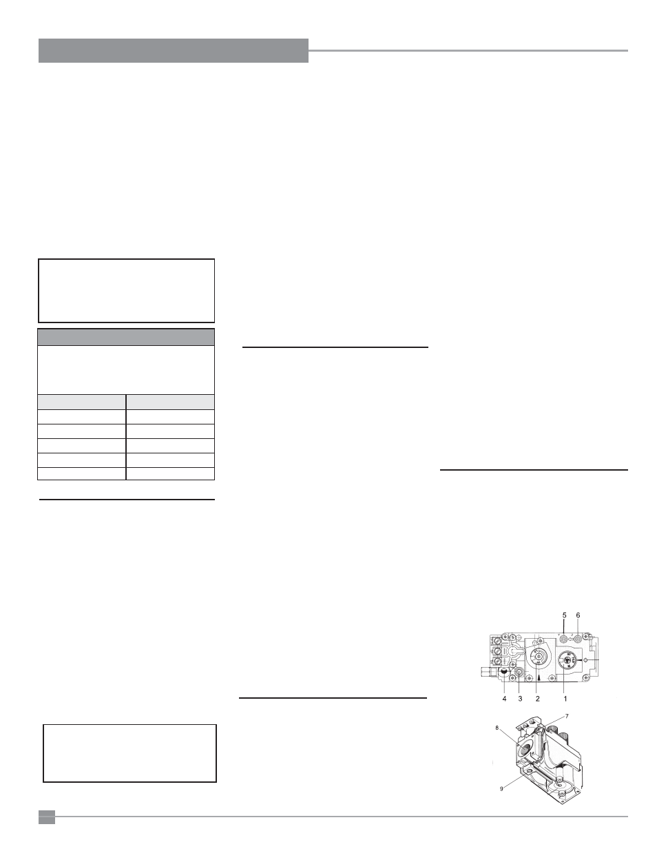
820 S.I.T. VALVE
DESCRIPTION
1) Gas on/off knob
2) Manual high/low adjustment
3) Pilot
Adjustment
4) Thermocouple Connection - option
5) Outlet Pressure Tap
6) Inlet
Pressure
Tap
7) Pilot
Outlet
8) Main Gas Outlet
9) Alternative TC Connection Point
CAUTION
Do not connect the millivolt
wall thermostat wires
to the 120V wires.