Communicating bath, Using magnetic locks, Cb401b – SDC UR-1 User Manual
Page 6: Cb401a
Switch No:
off
off
Position
SW1 SW2
off
SW3
off
SW4
C NO C NO - NO C NC - NO C NC
- +
TRIG A TRIG B
RELAY A
RELAY B
PWR
Communicating Bath
w
D
A
w
D
B
+
-
+
-
DPS
*
DPS
DPS switches should
be in the Closed state
with the doors Closed
*
EMERGENCY
RELEASE
PUSH
TO UNLOCK DOOR
WHT
YEL
ORG
CB401B
RED
RED
LAMP
EMERGENCY
RELEASE
PUSH
TO UNLOCK DOOR
WHT
YEL
ORG
CB401B
RED
RED
LAMP
WHT
YEL
ORG
CB401A
RED
RED
LAMP
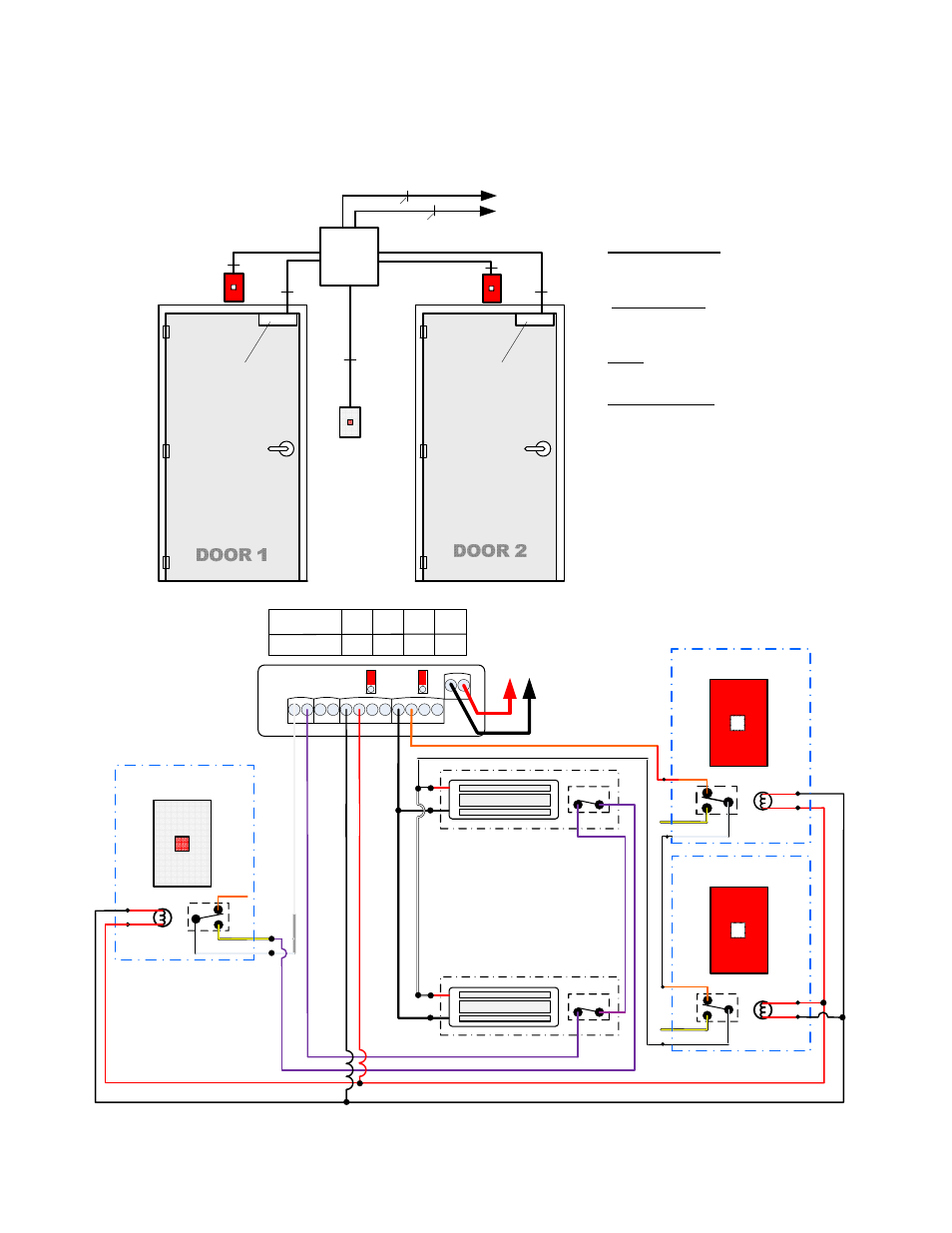
Using Magnetic Locks
Door 1
Door 2
Push to
Lock or Unlock
Both Doors
(Inside)
1
2
To
12vdc or 24vdc
Power Supply
+ -
BATHROOM LOCK
BOTH DOORS MUST BE
CLOSED TO LOCK
PUSH TO
LOCK OR UNLOCK
LIGHT ON DOOR LOCKED
Set to “CR Mode”
4 COND
4 COND
4 COND
Magnetic Lock
x
DPS
CB401A
PUSH
BUTTON
(INSIDE)
CB401B
PUSH
BUTTON
4 COND
CB401B
PUSH
BUTTON
4 COND
Magnetic Lock
x
DPS
Method of Operation
Both doors shall be normally unlocked.
System Activation: All doors must be closed to
lock. Pressing the CB401A Push Button will lock
all the doors.
Egress: When the doors are locked, pressing the
CB401A Push Button again unlocks all the doors.
Emergency Release: When the doors are locked,
activating either of the CB401B Emergency Push
Buttons will unlock both doors. Both doors will
unlock automatically via signal from the fire
panel.
When used with an SDC 631RF power supply,
Both doors will unlock automatically via signal
from the fire panel.
TO N/C FIRE ALARM INTERFACE
TO 115 VAC PRIMARY VOLTAGE
2 COND
3 COND
631RF
x
UR1
Power
Supply
MAGNETIC LOCK
MAGNETIC LOCK
P:\INSTALLATION INST\POWER SUPPLY\INST-UR-1.vsd Rev H 04-14 Page 6