Td/lr mode, Interlock b, Interlock a – SDC UR-1 User Manual
Page 4: 2 modules are required)
Latching
Lock / Unlock
Switch No:
ON
ON
Position
SW1 SW2
off
SW3
ON
SW4
C NO C NO - NO C NC - NO C NC
- +
TRIG A TRIG B
RELAY A
RELAY B
PWR
TD/LR Mode
w
D
A
w
D
B
Fail Safe
Lock
Fail Secure
Lock
NC
COM
NO
DRY
CONTACTS
Timed
P:\INSTALLATION INST\POWER SUPPLY\INST-UR-1.vsd Rev H 04-14 Page 4
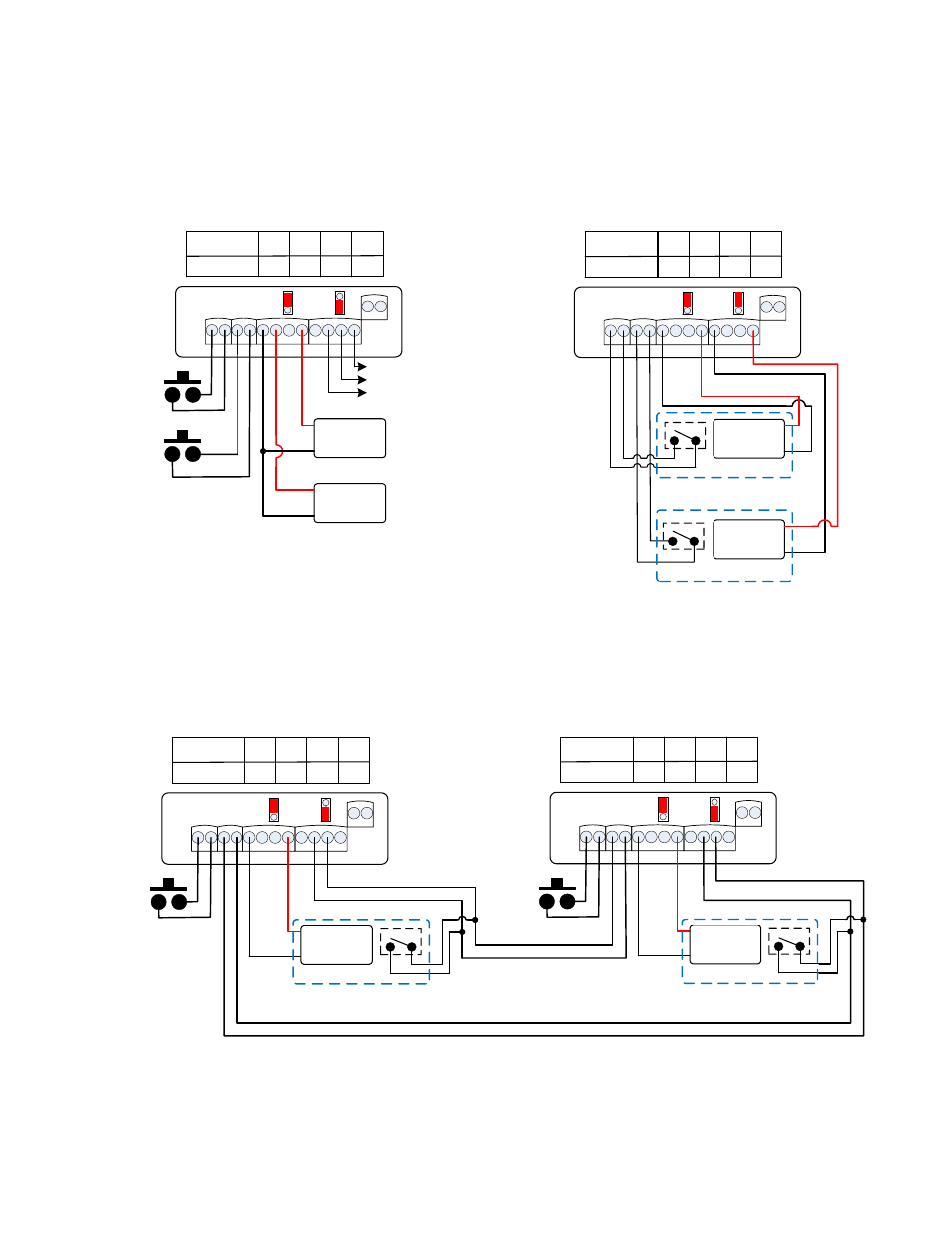
Interlock B
(2 Modules are Required)
C NO C NO - NO C NC - NO C NC
- +
TRIG A TRIG B
RELAY A
RELAY B
PWR
w
D
A
w
D
B
Access
Control
A
Fail Safe
Lock
DPS
+
-
*
C NO C NO - NO C NC - NO C NC
- +
TRIG A TRIG B
RELAY A
RELAY B
PWR
w
D
A
w
D
B
Access
Control
B
Fail Safe
Lock
DPS
+
-
*
Door B
Door A
DPS switches should
be in the Open state
with the doors Closed
*
Method of Operation:
Both doors are normally closed and locked. Unlocking or opening the other door will make the other door incapable of being unlocked.
Switch No:
Position
SW1 SW2 SW3 SW4
off
ON
off
ON
Switch No:
off
ON
Position
SW1 SW2
off
SW3
ON
SW4
Switch No:
ON
off
Position
SW1 SW2
ON
SW3
off
SW4
C NO C NO - NO C NC - NO C NC
- +
TRIG A TRIG B
RELAY A
RELAY B
PWR
Interlock A
w
D
A
w
D
B
Fail Safe
Lock
Door A
Door B
DPS
+
-
DPS switches should
be in the Open state
with the doors Closed
*
*
Fail Safe
Lock
DPS
+
-
*
Method of Operation:
Both doors are normally closed and Unlocked. Opening either door will
Lock the other door.
WARNING!: The UR board Output Relays must be protected against inductive kickback generated when power is removed from an inductive load
(e.g., electric strikes). Refer to the lock manufacturer's installation manual or contact the manufacturer for kickback protection recommendations.