SDC UR-1 User Manual
Ur-1
INSTALLATION INSTRUCTIONS - MODEL UR-1
UNIVERSAL RELAY MODULE
801 Avenida Acaso, Camarillo, Ca. 93012 • (805) 494-0622 •
www.sdcsecurity.com • E-mail: [email protected]
Any suggestions or comments to this instruction or
product are welcome. Please contact us through
our website or email [email protected]
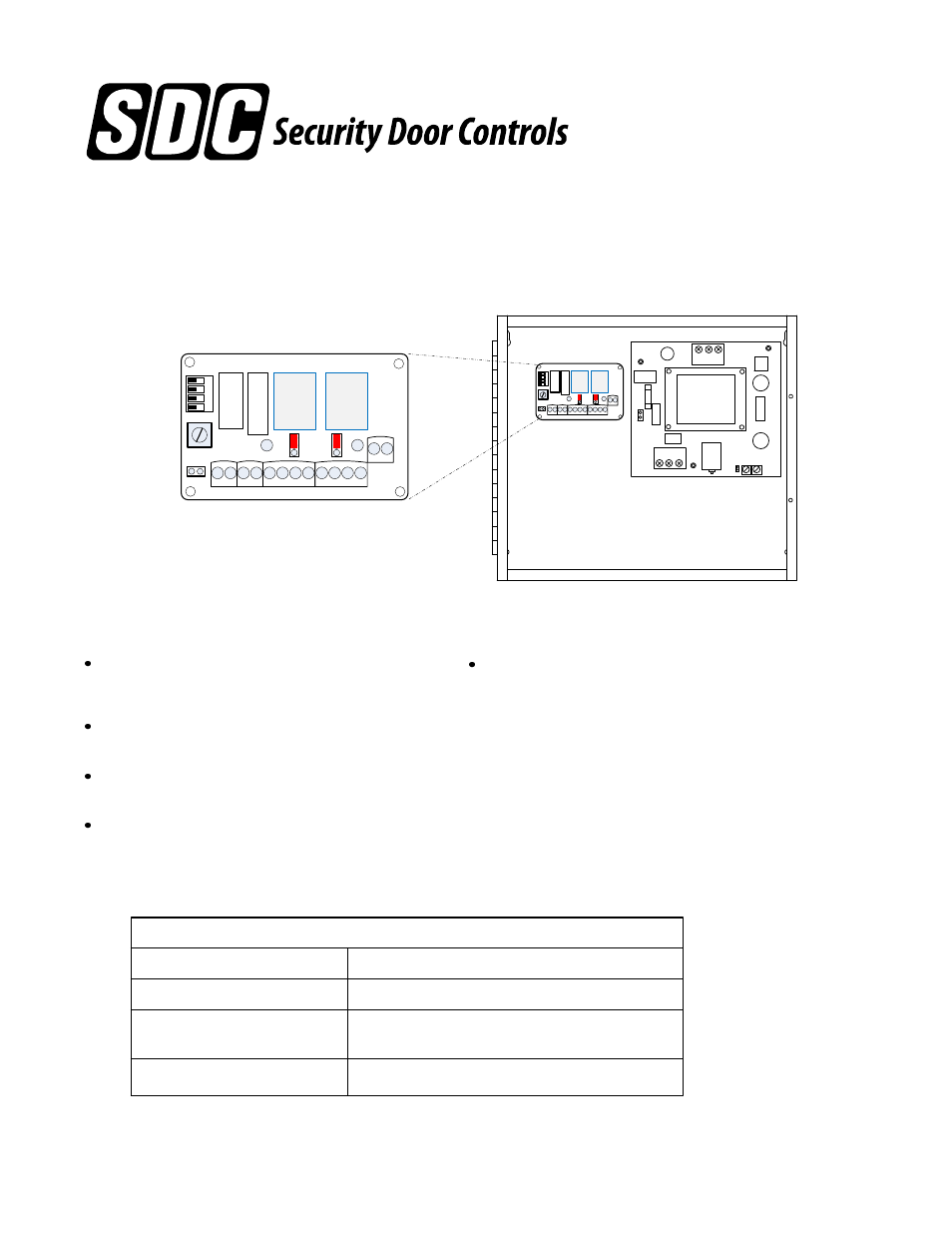
C NO C NO - NO C NC - NO C NC
- +
TRIG A TRIG B
RELAY A
RELAY B
PWR
w
D
A
w
D
B
1
2
3
4
J1
UR-1
UR-1 UNIVERSAL
RELAY MODULE
Fits all SDC Power Supplies. Requires
1 Module space. Supplied with mounting
screws and standoffs for J-box mounting.
C NO C NO
- NO C NC
- NO C NC
- +
TRIG A TRIG B
RELAY A
RELAY B
PWR
w
D
A
w
D
B
1
2
3
4
J1
UR-1
INPUT VOLTAGE
INPUT CONTROLLER CURRENT
12 or 24VDC +/- 10%
120/175mA
OUTPUTS
2 ea 10 amp @ 30VDC (resistive) SPDT Lock Outputs
(Configurable Wet or Dry). Wet output voltage is the
same as the module power IN voltage.
UR-1 TECHNICAL SPECIFICATIONS
DIMENSIONS
3.20"W x 2.00" L x 1.0" H
[81.28mm W x 50.8mm L x 25.4mm H]
INPUTS
2 ea Dry Signal Inputs
Field selectable relay modes include:
- Conventional Relay (CR)
- Dual Conventional Relay (2X CR)
- Time Delay Relay (TD) – 1 to 60 Seconds
- Dual Time Delay Relay (2X TD)
- Latching Relay (LR) – Separate Latch and Release Inputs
- Dual Latching Relay – (2X LR) Pulse On, Pulse Off Inputs
- Time Delay/Latching Relay
- Interlock A (airlock)
- Interlock B (2 modules required)
FEATURES AND BENEFITS
Microprocessor based relay controller that provides
multiple, field selectable operational modes for up to
two door stations.
Each output relay is field selectable as a dry contact
or voltage output.
Centralized wiring for all locks, access controls,
monitoring contacts and peripheral equipment.
1 or 2 controllers may be installed in SDC 600 series
power supplies
P:\INSTALLATION INST\POWER SUPPLY\INST-UR-1.vsd Rev H 04-14 Page 1