Dual cr mode, Cr mode, Td mode – SDC UR-1 User Manual
Page 2: Dual td mode, Power supply, Ur-1
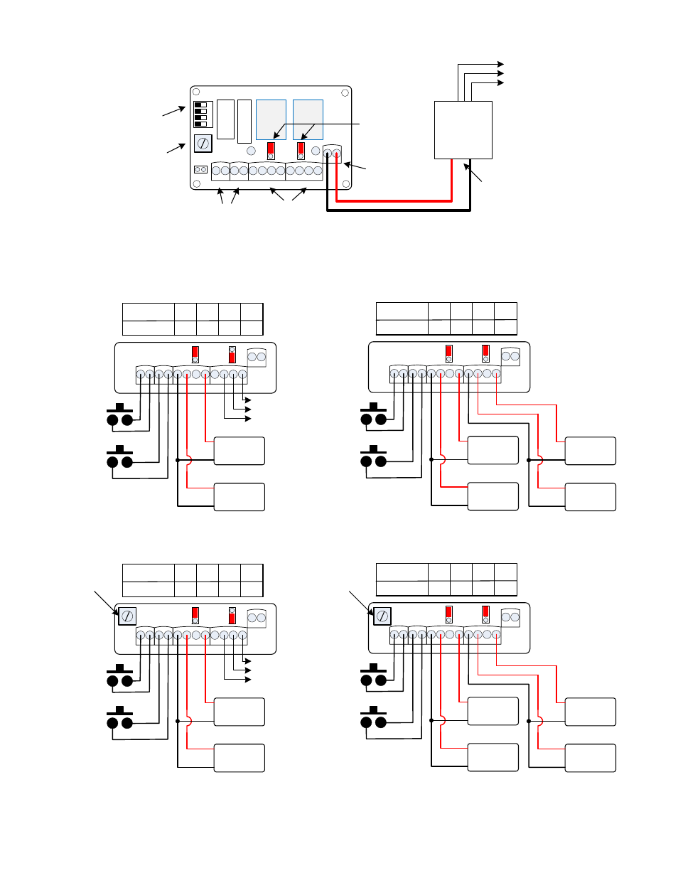
Switch No:
off
ON
Position
SW1 SW2
off
SW3
off
SW4
C NO C NO - NO C NC - NO C NC
- +
TRIG A TRIG B
RELAY A
RELAY B
PWR
Dual CR Mode
w
D
A
w
D
B
Fail Safe
Lock
Fail Secure
Lock
Push and hold
to Unlock
Fail Safe
Lock
Fail Secure
Lock
Door A
Door B
Access
Control
Access
Control
B
A
+
-
+
-
+
-
+
-
Switch No:
off
off
Position
SW1 SW2
off
SW3
off
SW4
C NO C NO - NO C NC - NO C NC
- +
TRIG A TRIG B
RELAY A
RELAY B
PWR
CR Mode
w
D
A
w
D
B
Fail Safe
Lock
Fail Secure
Lock
NC
COM
NO
DRY
CONTACTS
Access
Control
Access
Control
A or B
A or B
Push and hold
to Unlock
+
-
+
-
Switch No:
off
off
Position
SW1 SW2
ON
SW3
off
SW4
C NO C NO - NO C NC - NO C NC
- +
TRIG A TRIG B
RELAY A
RELAY B
PWR
TD Mode
w
D
A
w
D
B
Fail Safe
Lock
Fail Secure
Lock
NC
COM
NO
DRY
CONTACTS
Access
Control
Reset
Push to
Activate
+
-
+
-
Time Adj
1 – 60 Sec
Switch No:
off
off
Position
SW1 SW2
off
SW3
ON
SW4
C NO C NO - NO C NC - NO C NC
- +
TRIG A TRIG B
RELAY A
RELAY B
PWR
Dual TD Mode
w
D
A
w
D
B
Fail Safe
Lock
Fail Secure
Lock
Push to
Activate each
Timer
Fail Safe
Lock
Fail Secure
Lock
Door A
Door B
Access
Control
Access
Control
B
A
+
-
+
-
+
-
+
-
Time Adj
1 – 60 Sec
(Both A & B same
time setting)
C NO C NO - NO C NC - NO C NC
- +
TRIG A TRIG B
RELAY A
RELAY B
PWR
w
D
A
w
D
B
1
2
3
4
J1
Power In
12/24 vdc
Output
Relays
Inputs
Time
Adj
Program
Dip Switches
Relay Output
Jumpers
W = Wet (voltage)
To
AC Mains
Power
Supply
+ -
12/24 vdc
D = Dry
UR-1
Push & Release
to Reset
P:\INSTALLATION INST\POWER SUPPLY\INST-UR-1.vsd Rev H 04-14 Page 2
WARNING!: The UR board Output Relays must be protected against inductive kickback generated when power is removed from an inductive load
(e.g., electric strikes). Refer to the lock manufacturer's installation manual or contact the manufacturer for kickback protection recommendations.