Schwank STSp-WP User Manual
Page 8
SP-MSWP-BX-09A
STSp-WP Manual
RD: MAY 2004
RL: 9
KH
Page 4
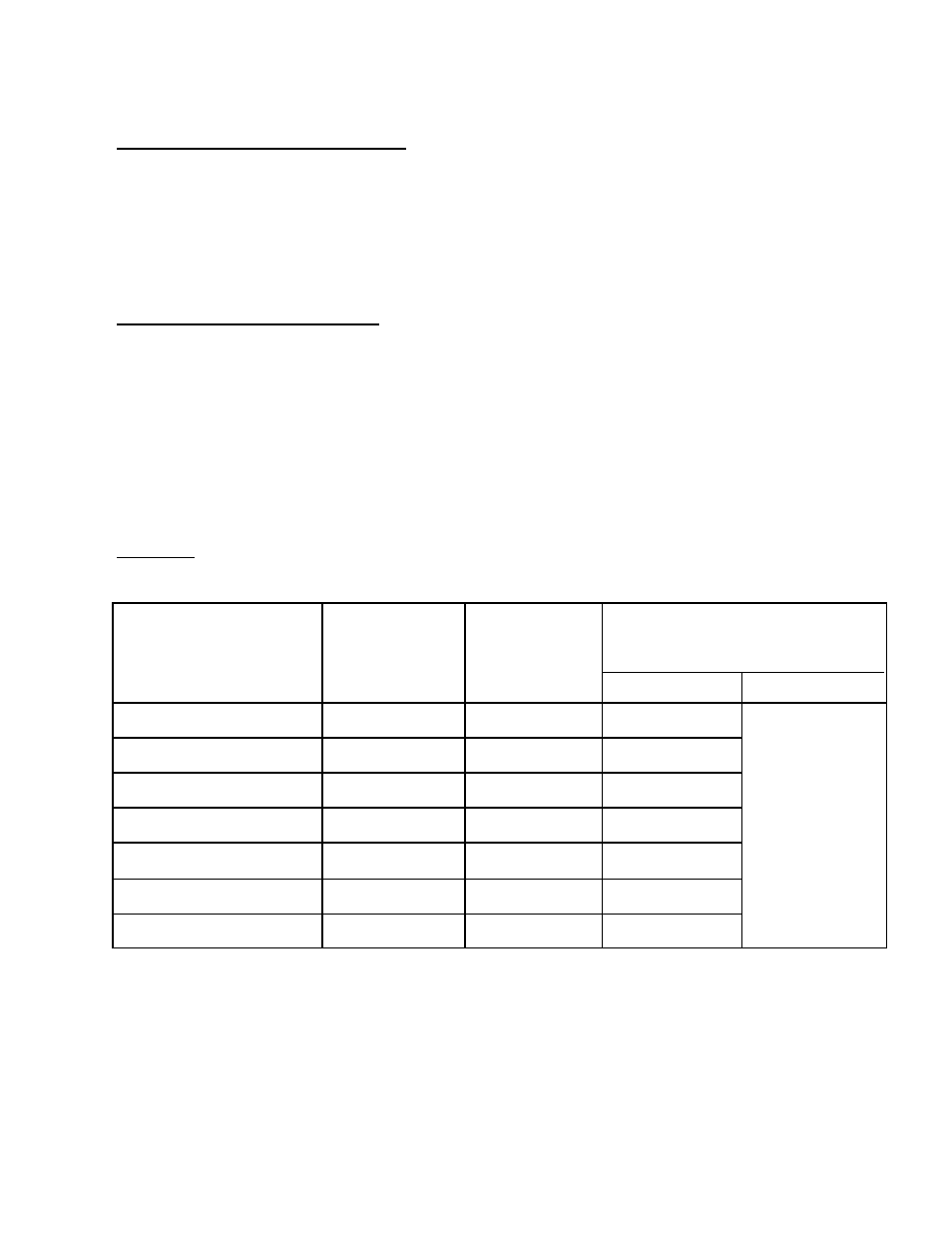
MODEL
MOUNTING
HEIGHTS
(FEET)
MAXIMUM
DISTANCE
BETWEEN
HEATERS (FEET)
DISTANCE – OUTSIDE WALL
TO HEATER LONG AXIS
PARALLEL TO WALL (FEET)
HORIZONTAL ANGLE
STSp200-WP
18 – 25
50
17 – 25
COMBUSTIBLE
CLEARANCE
STSp175-WP
18 – 25
50
17 – 25
STSp155-WP
16 – 21
45
15 – 20
STSp130-WP
15 – 21
40
15 – 20
STSp110-WP
13 – 19
35
13 – 18
STSp80-WP
10 – 16
30
12 – 16
STSp-60-WP
8 – 14
25
11 – 15
5. PRE-INSTALLATION SURVEY
The Schwank STSp-WP heating system
must have gas piping of the correct diameter,
length, and arrangement to function properly.
For this reason, a layout drawing is neces-
Carefully survey area to be heated. For best
results, whenever possible, place burner and
combustion chamber in coldest area.
6. MOUNTING CLEARANCES
This heater must be mounted with minimum
clearances between the reflector surface and
combustibles, as shown in FIGURE 1 (page
5), TABLE 3 (page 5).
For recommended heater placement, refer to
TABLE 2 (below).
Heater position relative to building
construction and equipment must provide a
minimum clearance of 24 inches from the end
of burner housing to allow for servicing and
cleaning of burner, blower and controls.
TABLE 2 RECOMMENDED HEATER PLACEMENT FOR INDOOR APPLICATIONS
IMPORTANT: Continuous operation of single or multi-heater
must not cause combustible material or materials
in storage to reach a temperature in excess of 160
O
F.