System configuration, Important – Schwank STSp-WP User Manual
Page 10
SP-MSWP-BX-09A
STSp-WP Manual
RD: MAY 2004
RL: 9
KH
Page 6
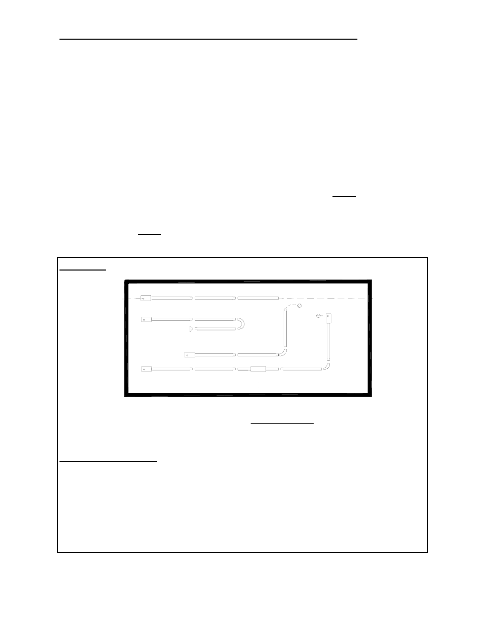
7. SYSTEMS INCORPORATING 90
O
ELBOWS AND 180
O
ELBOWS
The STSp-WP Series radiant tube heater can
be installed in configurations as illustrated in
FIGURE 2. (below) with a maximum of two
90
o
or one 180
o
elbow per heater. The use of
radiant elbows reduces the total maximum
vent allowable. See FLUE VENTING in
SECTION 11 (page 14).
Both the 90
o
and 180
o
elbows are shipped as
a kit, with one coupler kit and two end plate
hangers to close off the reflector ends
around the elbow(s). Reflectors must be
secured with four screws to each of the end
plate hangers, SEE FIGURE 3, (page 7) and
FIGURE 6 (page 8).
On Models STSp-WP 200, 175 a minimum of 30´ of straight
radiant tube and on Models STSp-WP 155, 130 and 110, a
minimum of 20´ of straight radiant tube must be connected
to the burner before any turns are made. On Models STSp-
WP 80, and 60, a minimum of 10´ of straight radiant tube
must be connected to burner before any turns are made.
FIGURE 2 SYSTEM CONFIGURATIONS
System Configuration
1 Straight line
2 “U” tube with 180º elbow kit
3 “L” tube with 90º elbow kit
4 Twined tubes into common TEE flue vent
Venting Options
A Flue vent through wall 4”
B Flue vent through wall or roof 6”
C Flue vent through roof
D Flue vent into building, exhaust fan
interlocked with heater
E Combination air intake from outside
through wall
F Combination air intake from outside
through roof
G Combination air intake from inside
building
IMPORTANT:
A
F
C
G
D
E
B
1
2
3
4
G
G