Butt sight glass ring to end plate hanger – Schwank STSp-WP User Manual
Page 11
SP-MSWP-BX-09A
STSp-WP Manual
RD: MAY 2004
RL: 9
KH
Page 7
8. SUSPENSION SYSTEM
End plate hangers are provided to support
reflectors and tubes at both ends of heater,
that is at burner and at flue, see FIGURE 3
(below), FIGURES 4,5,6 (pages 7, 8). Wire
hangers are provided to support reflectors
and tubes along the full length between the
two end plate hangers, SEE FIGURES 4,5
(pages 7, 8) and FIGURES 7,9 (page 9).
The system configuration and available
support locations must be considered to
locate the radiant tubes correctly. A wire
hanger must support the tube and reflector at
each side of a coupling connection.
Labour and material can be reduced by
locating the heater (system configuration
permitting) directly under structural
Chain is recommended for hanging the tube
system, connecting the hangers to structural
support as illustrated in FIGURE 8 (page 9).
To support burner and keep it level, a
separate suspension chain must be attached to
the eye hook at flange end of burner angled
slightly back over burner, FIGURE 5 (page
8). This will permit normal expansion and
contraction of the tube system. If rigid de-
vices such as rods are used in place of chain,
then swing joints or other means of sufficient
length must be provided to compensate for
expansion. This expansion can be consider-
able on high Btu and long tube models.
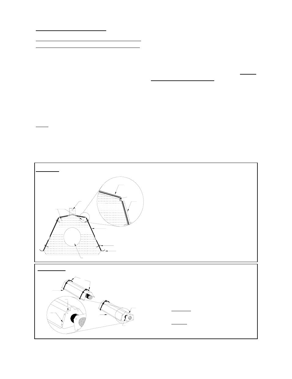
FIGURE 3 MOUNTING REFLECTOR TO END PLATE HANGER
1 End Plate Hanger Flange
protruding over the Reflector
2 End Plate Hanger Flange
protruding under the reflector
3 Screws securing Reflector to
End Plate Hanger
4 Chain Hole for horizontal
suspension
5 Chain Hole for up to 45º
suspension
6 Opening for Tube
7 Focus Shield Reflector
FIGURE 4 HANGER ARRANGEMENTS 1 Two Wire Hangers per Each
Middle Section
2 Use End Plate Hangers at
Burner & Flue Ends (& each
side of any elbow)
3 End Plate Hanger Flange
UNDER Reflector
4 End Plate Hanger Flange
OVER Reflector
5
Butt Sight Glass Ring to
End Plate Hanger
6
5
4
7
3
1
2
1
7
1
5
2
4
3
ADDITIONAL
TUBE(S)
FIRST
TUBE