Figure 5 typical hanger & support spacing, Figure 6 end plate hanger/elbow installation – Schwank STSp-WP User Manual
Page 12
SP-MSWP-BX-09A
STSp-WP Manual
RD: MAY 2004
RL: 9
KH
Page 8
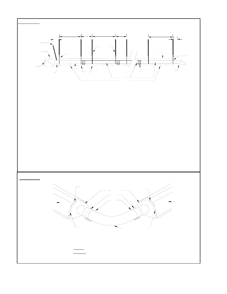
FIGURE 5 TYPICAL HANGER & SUPPORT SPACING
5. Sight Glass
6- Aluminized Tube with Flange
7– Tube Coupler
8- Painted Steel Tube(s)
1.End Plate Hangers
2- Wire Hangers
3- Burner Assembly
4- Combustion Air Intake
9– Focus shield Reflector ***
10- Flue Vent terminal
11- Burner Support Chain****
12- Hanger Support Chains
13- Reflector Stabilizer **
FIGURE 6
END PLATE HANGER/ELBOW INSTALLATION
1
. End-Plate-Hangers 5. 90
0
(shown) or 180
0
Elbow
2. Focus Shield Reflectors 6. Tube/Elbow Coupler
3. End-Plate-Hanger Flange OVER Reflector elbow 7. Point at which Swaged tube fits into elbow
4. End Plate Hanger Flange UNDER Reflector and Swaged end of elbow fits into tube.
1
2
2
3
3
4
4
5
6
7
10
13
2
11
4
3
5
6
8
7
9
1
1
12
3"
4"
"ALL TUBES MUST BE SUSPENDED BY TWO (2) HANGERS PER 10' LENGTH,
MOUNTED APPROXIMATELY 6" TO 12" IN FROM EACH TUBE END.
Note Exception: First and last hanger (end plate hangers) must be mounted 4” away from end of tube
* Distances shown are recommendations and may be varied to match field requirements.
** This should only be used if the reflector is mounted on an angle.
*** Refer to section 9: Focus Shield Reflector Installation (page 11).
**** The angle is very critical