Schwank SER(IR) User Manual
Page 8
GP-MSER-BX-11A
SER / IR Manual
RD: March 2006
RL: 11A
KH
A
F
C
G
D
E
B
1
2
3
4
G
G
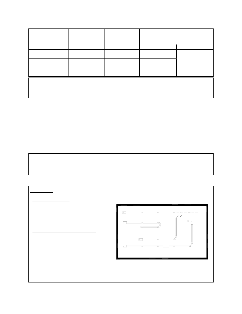
5. SYSTEMS INCORPORATING 90° BENDS AND 180° ELBOWS
Page 4
The SER / IR Series radiant tube heater can be installed in configurations as illustrated in
FIG: 2 (below) with a maximum of two 90
o
or one 180
o
elbow per heater. The use of
radiant elbows reduces the total maximum vent allowable. See SECTION 9 (page 10): Flue
Venting. Both the 90
o
and 180
o
elbows are shipped as a kit with one clamp and two end caps to
close off the reflector ends each side of the elbow (s). The reflectors must be secured with four
screws to each of the end caps. SEE FIG: 3 (PAGE 5).
FIGURE 2 SYSTEM CONFIGURATIONS
System Configuration
1 Straight line
2 “U” tube with 180-degree elbow kit
3 “L” tube with 90-degree elbow kit
4 Twinned tubes into common TEE flue vent
IMPORTANT: On SER / IR 60 and 45 models, a minimum of 10’ of straight
radiant tube must be connected to the burner before any
elbow.
IMPORTANT: Continuous operation of single or multi-heater placement
must not cause any combustible material in storage to
reach a temperature in excess of 160°F.
TABLE 3 RECOMMENDED HEATER PLACEMENT
MODEL
MOUNTING
HEIGHTS
(FEET)
MAXIMUM
DISTANCE
BETWEEN
HEATERS (FEET)
DISTANCE – OUTSIDE WALL
TO HEATER LONG AXIS
PARALLEL TO WALL (FEET)
HORIZONTAL ANGLE
SER / IR 60
8 - 14
25
11 – 15
COMBUSTIBLE
CLEARANCE
SER / IR 45
6 - 10
20
8 – 12
SER / IRU 60
8 – 14
25
11 – 15
Venting and Combustion Air Options
Flue Vent:
A Through wall 4”
B Through wall or roof 6”
C Through roof
D Into building, exhaust fan interlocked with
heater
Combustion Air Intake:
E from outside through wall
F from outside through roof
G from inside building