Together – Schwank SER(IR) User Manual
Page 12
GP-MSER-BX-11A
SER / IR Manual
RD: March 2006
RL: 11A
KH
Page 8
FIGURE 8: END CAP/ ELBOW INSTALLATION
5. 90° Elbow
6. End of Swaged Tube (fully inserted)
7. Coupler
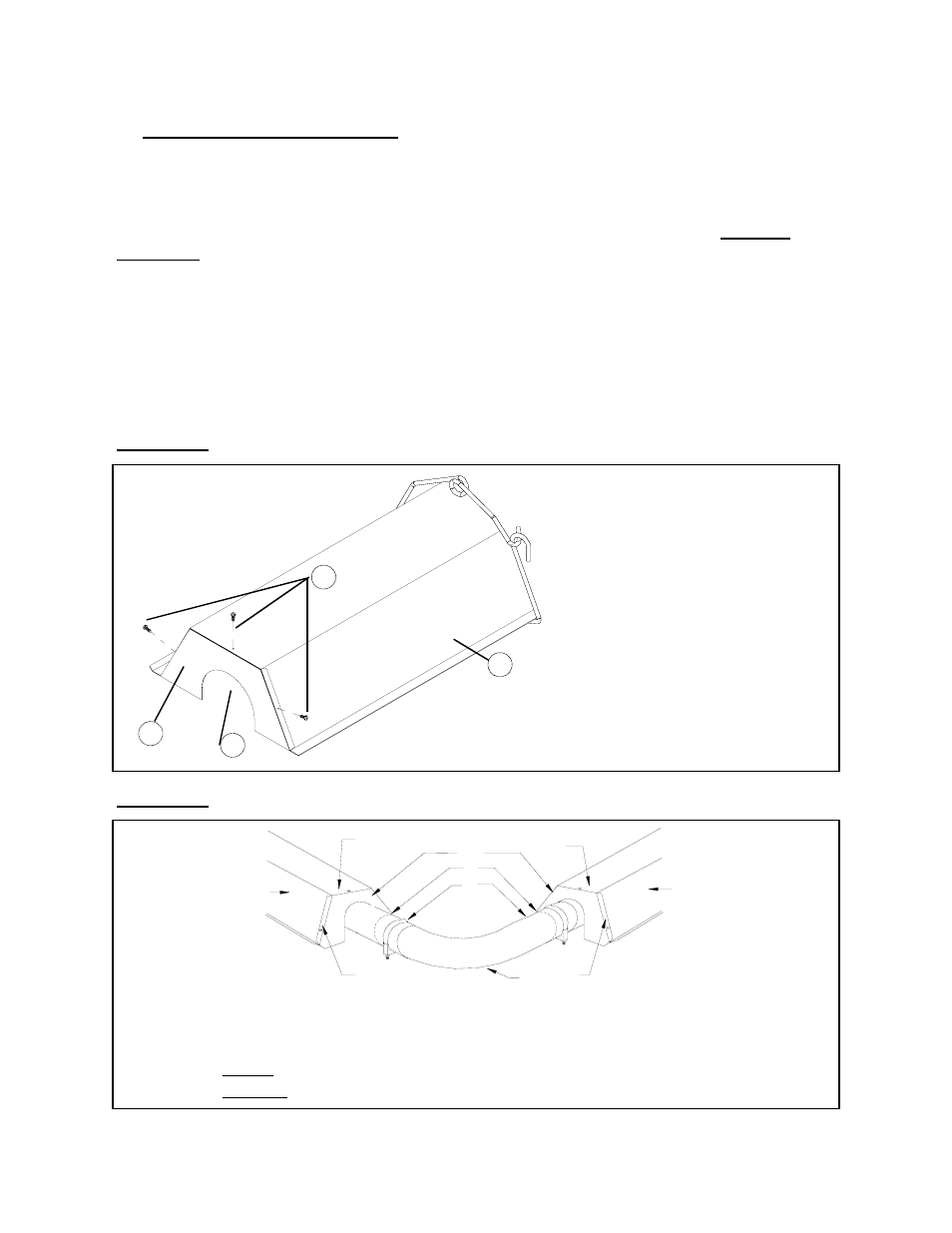
FIGURE 7: MOUNTING REFLECTOR TO END CAP
8. REFLECTOR INSTALLATION
After burner and tubes have been installed, slide the reflectors one at a time, into the wire hang-
ers. Install an end cap on the reflector at the end of each straight run (Fig. 7 & 8). As each suc-
cessive reflector is installed on an in-line installation, the ends of the reflectors will overlap to
provide continuous coverage over the entire tube system. The overlapping joints
MUST BE
FASTENED
together.
Note that for both horizontal and angle mounting, the tube must be level. Improper mounting
can result in overheating of controls and combustible materials. Use only non-combustible
mounting hardware. Side reflectors can be added to the heaters as an option. They should be
secured directly to the focus shield reflector using "S" hooks or chain. Drill three holes into the
focus shield reflector flange along side, matching up with three holes already in side reflector.
Mount side reflector as close as possible to the focus shield reflector.
1. Reflector End Caps
2. Reflectors
3. End Caps OVER Reflector
4. End Caps UNDER Reflector
1
Reflector End Cap Flange protrud-
ing over and under the Reflector
2
Screws securing Reflector to End
Cap
3
Opening for Tube
4
Reflector
2
1
3
4
1
2
2
3
3
4
4
5
6
7