Schwank SER(IR) User Manual
Page 15
GP-MSER-BX-11A
SER / IR Manual
RD: March 2006
RL: 11A
KH
Page 11
As an option two heaters may be vented through an approved common 4" X 4" X 6" flue Tee,
(Tee supplied by manufacturer) with a maximum of two per heaters per Tee. Both of the heat-
ers must then be controlled by one single common thermostat or "ON/OFF" operating switch.
All vent pipe used with a slip-fit connection must be mechanically secured. Where the vent pipe
passes through areas where the ambient temperature is likely to produce condensation of the
flue gases, the vent pipe shall be insulated with a suitable material as approved and specified
by the insulation manufacturer. Insulation may be subject to temperatures over 500° F. The vent
system must always be adequately supported to prevent sagging.
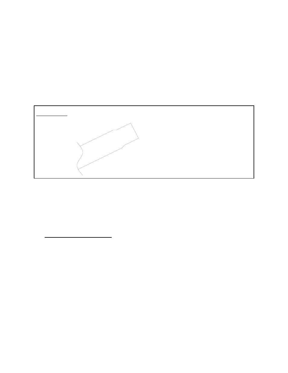
FIGURE 12: FLUE VENT CONNECTOR
The end of the Tube is Swaged and will accommodate regular “C” Vent for venting to
outside. The “C” Vent connection to the radiant tube swaged end, must be fitted over,
and pushed beyond the swage until it fits snugly, then secured with sheet metal screws.
END OF TUBE
In installations where chlorinated hydrocarbons are in use, such as Tri-
chloroethylene, Chloroethylene Nu or Refrigerants, it is essential that
combustion air be brought in from non-contaminated areas. Burning
the fumes from these gases will create Hydrochloric Acid fumes, which
are detrimental to humans, equipment and buildings.
10. COMBUSTION AIR DUCT
Where heater is operated in a negative air condition or in contaminated air atmosphere such as
woodworking shops, air for combustion must be ducted from outside to intake flange on burner
blower. Combined maximum length of combustion air duct and flue vent is 50' for SER / IR 45.
The total maximum vent allowable is reduced by 10' for every 90
o
vent elbow installed.
CAUTION
: