Schwank builderSchwank S100U User Manual
Page 20
20
S100-F / ITB-F I&O Manual
IM101230
RD: SEP 2014
RL: 11A
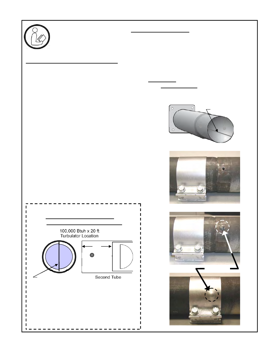
SPECIAL COUPLER INSTALLATION
1. Install first tube so that the welded seam
along the tube length is in the lower half of
the tube facing downward
2. Slide the loosened tube coupler on to the
first tube, past the swage
3. The second tube is supplied with a ¼” hole
in the tube at the female end.
4. Slide second tube over swaged end of first
tube so that ¼” hole is located 90° up from
the bottom (3 or 9 o’clock position)
5. Note that the spine of the turbulator should
be oriented in a vertical position
6. Through the existing ¼” hole , drill a ¼”
hole through the wall of the first tube
7. Insert ¼” rivet into the hole
8. Slide coupler into position – half onto each
tube – covering the rivet head
9. Tighten coupler bolts to 40 ft-lb
10. Install reflectors
9.3 SPECIAL COUPLING: 100,000 Btuh x 20 ft
NOTE: The joint of 1ST & 2ND tubes of the 100,000 x 20 ft heater experiences strong
forces of expansion. Follow instructions below for special coupling of the tubes and orien-
tation of the turbulator in the 2nd tube..
FIGURE 15 SPECIAL COUPLING:
100,000 x 20 ft
- Fasten Second Tube to First Tube -
Steps 2
thru 6
Step 7
Steps 8
& 9
1/4” Rivet
VIEW INSIDE TUBE: Ensure the 8 ft (2.4 m) tur-
bulator installed in the second tube is oriented
with its spine in a vertical position, and located at
the vent end of the tube.
This will result in the best performance and radi-
ant output from the system.
Step 5
NOTE:
100,000 Btuh x 20 ft Heater
TURBULATOR ORIENTATION
with 8 ft turbu-
2 ft
Install tube with turbula-
tor spine in vertical posi-
tion for best performance
Step 1
Welded seam in lower
half of tube, facing
downward
TOOLS REQUIRED:
Electric Drill
1/4” Drill Bit (supplied)