S100u/itbu ‘u’-tube system – Schwank builderSchwank S100U User Manual
Page 17
17
S100-F / ITB-F I&O Manual
IM101230
RD: SEP 2014
RL: 11A
9.2
S100U/ITBU ‘U’-TUBE SYSTEM
~ BURNER AND TUBE INSTALLATION
For “Straight-Tube” Systems S100 / ITB refer to section 9.1 page 15
IMPORTANT SPECIAL NOTES: READ FIRST
1. S100U/ITBU 175 & 200 ONLY:
Special Tube Connection
-
Refer to Section 9.4, Fig 16
These input rates have an unpainted titanium alloy stainless steel first tube with a flange
(painted “white”), and an unpainted aluminized steel tube as the second tube; all subse-
quent tubes are hot rolled steel. The first tube (titanium alloy stainless steel ) will “glow
red” while heater is in operation - THIS IS A NORMAL CONDITION
2. TURBULATORS: Also refer to Table page 47
155 Models
(150,000 Btuh): 2 ft turbulator is supplied in the Burner Kit and field installed:
155 x 20 ft U heater: Insert 2 ft turbulator in end of third tube in the system (1st
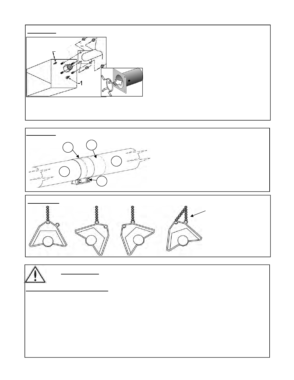
FIGURE 9: COUPLER INSTALLATION (NOTE: See Section 9.3 for ‘Special Couplers’ at
first tube joint: 100,000 x 20 ft & 175 / 200,000 models)
1. Tube
2. Swaged end of upstream tube
3. Tube
Coupler
4. Centre coupler over tube joint
Tighten coupler bolts to 40 ft-lbs.
Note: A gasket is not required between burner and tube flange
1. Fifth Nut (Holds Inner Burner to Housing - Do Not Loosen or Remove)
2.
Install Flame Rectifier inputs 110,000, 125,000, 200,000 LP:
A flame rectifier is supplied in the burner kit.
Prior to installing the burner onto the flanged
tube, insert the flame rectifier into the tube to
seat against the tube flange.
3. Insert four burner bolts through the tube flange, secure tightly with lock nuts.
4. Secure suspension chain to eye bolt to stabilize burner
FIGURE 8: BOLT BURNER TO TUBE FLANGE
FIGURE 10: HANGER / REFLECTOR ORIENTATION HORIZONTAL TO 45
0
FOR ANGLE LESS
THAN 45° USE
CHAIN TO BOTH
EYES ON HANGER
45°
45°
4
3
1
1
2
3
4
2