Schwank ultraSchwank EIH User Manual
Page 42
42
UHE-F / EIH-F I&O Manual
IM100205
RD: MAY 2014
RL: 06A
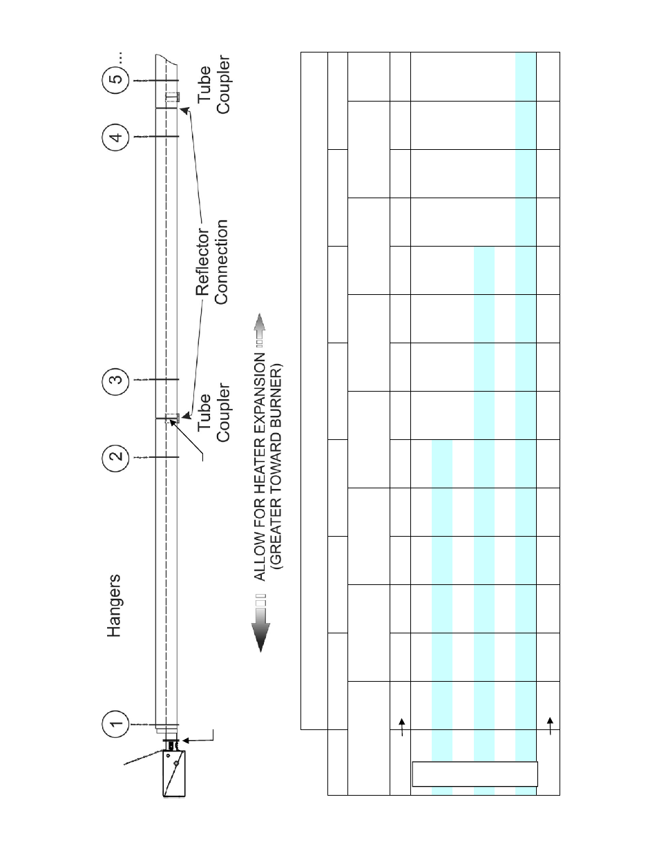
BEST R
A
N
G
ES FOR H
A
N
GER L
O
C
A
TION:
DISTA
NCE IN IN
CH
ES FROM FL
AN
GE AT B
U
R
N
ER E
N
D
Tube #
1 2 3
4 5
6
7
Tube
Co
nnect
io
n*
116 232
348 464
580 696
816
Re
fle
cto
r Conne
ctio
n
116 230
344 458
572 686
800
Han
ger #
1
2 3 4
5 6 7 8
9
10
11
12
13
14
20' 6
10
4-1
10
12
2-1
34
22
1-2
27
30'
6
10
4-1
10
12
2-1
34
21
8-2
24
23
6-2
42
335-341
40' 6
10
4-1
10
12
2-1
34
21
8-2
24
23
6-2
42
33
2-3
38
35
2-3
58
44
9-4
55
50'
6
10
4-1
10
12
2-1
34
21
8-2
24
23
6-2
42
33
2-3
38
35
2-3
58
44
6-4
52
46
8-4
74
56
3-5
69
60' 6
10
4-1
10
12
2-1
34
21
8-2
24
23
6-2
42
33
2-3
38
35
2-3
58
44
6-4
52
46
8-4
74
56
0-5
66
58
4-5
90
67
7-6
83
70'
6
10
4-1
10
12
2-1
34
21
8-2
24
23
6-2
42
33
2-3
38
35
2-3
58
44
6-4
52
46
8-4
74
56
0-5
66
58
4-5
90
67
4-6
80
70
0-7
06
79
1-7
97
Han
ger #
1
2 3 4
5 6 7 8
9
10
11
12
13
14
* The Tube
Cou
p
ler exte
nds 2 in
ch
es
each sid
e
of tube conn
ecti
on
Locate han
ge
rs a minim
u
m
of 2 inche
s
(5 cm) a
nd a
maximu
m of 22 inche
s
(56
cm) from the
edge of any tube coupl
er
System Length (ft)
25. HANGER LOCAT
ION: DISTANCE RA
NGES FROM FLANGE AT BURNE
R
Flange at
Burner End
Align 1st Reflector Connection
To center of 1st Tube Coupler