Schwank ultraSchwank EIH User Manual
Page 12
12
UHE-F / EIH-F I&O Manual
IM100205
RD: MAY 2014
RL: 06A
7. SYSTEMS
INCORPORATING
90° ELBOWS AND 180° ELBOWS
The radiant tube heater can be installed in configurations as illustrated in FIGURE 4 (below)
with a maximum of two 90° tube system elbows per heater. The use of elbows reduces the to-
tal maximum vent allowable by 10 feet for each 90°. (See Section 11 : Flue venting)
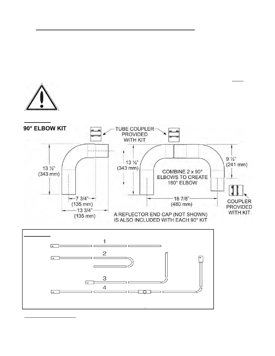
The 90° elbow kit (JS-0528-UE) is complete with one 90° elbow, one tube coupler, and one re-
flector end cap. For a 180° elbow two x 90° kits combine to create a 180°. The reflector must
be end-capped each side of an elbow - See FIGURE 6
IMPORTANT: Location of Elbow vs. Input: A minimum length of straight radiant tube must be
connected to the burner prior to any elbow as follows:
200 Mbh (60 kW) = 30 ft (7.6 m) prior to elbow
160 Mbh (45 kW) & 130 Mbh (38 kW) = 20 ft (6 m) prior to elbow
90 Mbh (23 kW) = 15 ft (4.6 m) prior to elbow
60 Mbh (18 kW) a minimum of 10 ft (3 m) straight tube before elbow.
System Configuration
1 Straight line
2 “U” tube with 2 x 90° elbow kits
3 “L” tube with one 90° elbow kit
4 Twinned tubes into common TEE flue vent
FIGURE 3 SYSTEM ELBOW KIT
FIGURE 4 SYSTEM CONFIGURATIONS
4” x 4” x 6” Vent Tee
JS-0508-UL
See Figure 8 for installed
orientation dimensions