Yes no, Page 2, Page 35 right right right wrong wrong – Schroth Racing AutoControl User Manual
Page 4
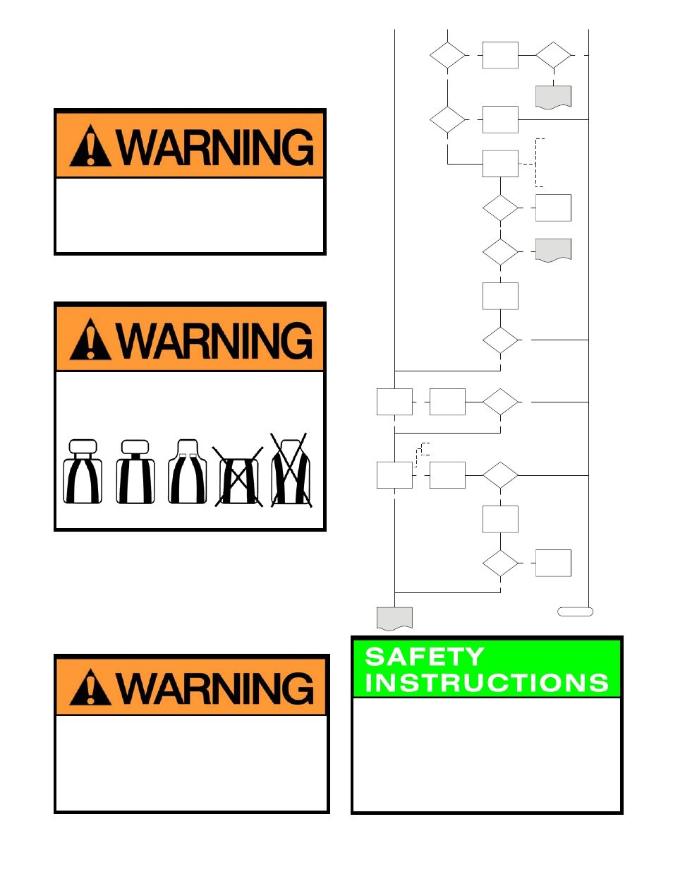
1. Is your vehicle listed in the Certified Vehicle List (Vehicle
Reference List)?
Compare your car’s specifications to the Make, Type No. and
Model Year of vehicle in the Certified Vehicle List (Vehicle
Reference List).
YES NO
Proper harness belt geometry requires that seat belt
anchor points be located within narrowly defined areas.
Therefore SCHROTH harnessbelts may only be installed
in SCHROTH approved vehicles for which proper
anchorage location and belt geometry has been
determined to exist.
2. Are there openings between the backrest and the headrest
of the seat? (See illustration below.)
YES NO
Harness belt system will not function properly and must
not be installed in vehicles equipped with seats having no
headrest or backrests with integrated headrest. (No
openings exist between the backrest and the headrest.)
Never create a new opening in the seats installed in your car.
3. If you intend to install the tail straps of the SCHROTH
harnessbelt system at the rear seat lap belt anchor point
a. have you made sure that the Certified Vehicle List
(Vehicle Reference List) allows or requires you to do so?
YES NO
b. is your vehicle equipped with a SCHROTH approved
seat? (see Certified Vehicle List (Vehicle Reference List)
and Legend on yellow pages)
YES NO
Installation to anchor points located lower than the front
seat backrest with an unapproved seat can result in
serious personal injury or death. Never install the
SCHROTH harnessbelt at these lower anchor points
unless this installation is allowed for your vehicle’s make,
model and model year and it is used with an approved
seat. [See Certified Vehicle List (Vehicle Reference List)
and heed all indexes.]
Page 2
Eye of ground
wire correctly
installed? See
pages 12 and
15.)
Ground
connection OK
between bolt
and chassis?
Replace defective
control wire
(red/black). Use
only SCHROTH
Spare Parts.
Replace defective
control wire
(red/black). Use
only SCHROTH
Spare Parts.
Replace defective
ground wire. Use
only SCHROTH
Spare Parts.
Check testing
points
and .
7
8
Eye properly
located?
Change position
of eye in the
assembly and
remove paint from
the thread.
Test again the
current between
testing point 6
and bolt head.
Ground
connection is
not OK. Please
go back to and
start again.
I
Function
O.K.?
Function
O.K.?
Function
O.K.?
Power at
testing point
?
5
Power at
testing point
?
7
Power at
testing point
?
8
yes
yes
yes
yes
yes
no
yes
yes
no
no
no
no
no
no
Test power between testing point and bolt head.
With a proper connection, the test lamp (voltmeter) will not show voltage.
6
1. Remove rubber
cover (see page 26).
2. Check the wire con-
nection and holder.
3. Power at testing
points and ?
(Positive and
negative terminals.)
7
8
Send retractor
to importer
for inspection.
Send retractor
to importer
for inspection.
no
no
yes
END
a) Make sure plugs
are well connec-
ted to the sensor.
b) Install the sensor
in a permanent
vertical position.
Power at
testing point
?
4
yes
no
Function
O.K.?
yes
no
Send retractor
to importer
for inspection.
Power
measureable?
• The recoil mechanism could remain permanently locked, if
the tail strap is disconnected from the separation buckle
while the ignition is off! The tail strap will be reeled in by
the recoil mechanism. If the latch of the belt hits the cover
without being slowed down, it might cause the recoil
mechanism to permanently lock up.
• If you disconnect the belt from the separation buckle,
make sure that the tail strap is slowly reeled in by manually
slowing the retraction. This will prevent the above-
described effect.
Page 35
right right right wrong wrong