Schroth Racing AutoControl User Manual
Page 19
7.3.1 Current supply wire
• The electrical current supply must be taken from a wire
that does not carry current when the ignition is turned off.
The wire selected must be "live" when the ignition is turned
on, but before the engine starts. The flow of electrical
current must not depend on the operation of any other
electrical system or device.
• We recommend use of the wire feeding the rear window
defogger, or any wire downstream from the fuse box
running from any terminal marked no.15 (non German
manufactured cars may use other symbols, numbers
and/or letters). Do not connect to the wire that powers the
computerized control system in the vehicle.
If the wiring for the harness belt system is connected to a
wire which carries current even when the ignition is off, the
electro-magnetic components of the harness belt system
could draw current continuously and discharge your car’s
battery while parked.
Check the wiring diagram of your vehicle for a suitable lead,
that can be easily used for proper installation as explained
above. If in doubt, please see your car dealer.
If you install two SCHROTH asm-autocontrol harnessbelt
systems in your car, you only have to connect the electrical
system of the left (driver side) retractor directly to a current
supply of the vehicle.
Be sure to follow the wiring instructions for the right (passenger
side) retractor in paragraph 7.3.3 below.
7.3.2 Connecting
To prevent damage to your car’s electrical system, only
make the following connections when the ignition
is turned off.
The fuse wire can be connected at any suitable position to the
current supply wire (from terminal 15 at fuse box in cars of
German manufacture) by the cable connector included.
Page 20
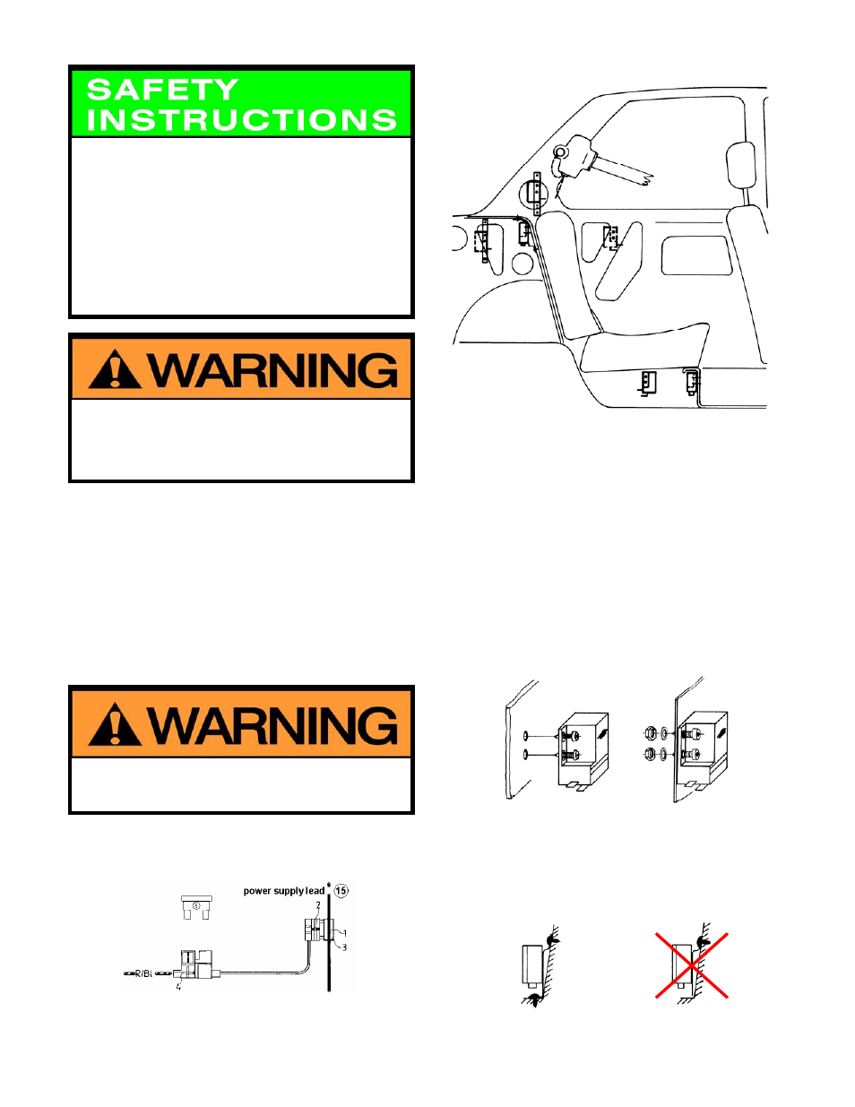
This figure indicates the most suitable positions for the sensor.
The figure shows a car body with interior panels removed.
Only install the sensor directly to a rigid vertical structure of the
car body that does not move.
The mounting holes must be in a straight vertical line and
25
/
32
"
(20 mm) apart. Drill the upper hole first to locate the sensor in
the desired position. Place the bubble level supplied on the top
surface of the sensor to check the front/rear and side-to-side
position. Mark the position for the second hole, drill and
remount the sensor. Recheck the position to make sure the
sensor is leveled.
for self tapping sheet
for 4 mm bolts, drill
metal screws, drill holes
holes
13
/
64
" (5 mm)
5
/
64
" (2 mm).
You can use sensor housing as a stencil.
Installation with the perforated metal strip
The perforated metal strip can be carefully bent and formed as
necessary for vertical installation of the sensor. Make sure that
both ends of the strap are fixed by screws for permanent and
rigid installation of the sensor on a non-moving structure.
right way wrong way
Page 17