2 writing data to the basic module, 3 handshaking logic, 1 general – SATEC SLC500 User Manual
Page 10
10
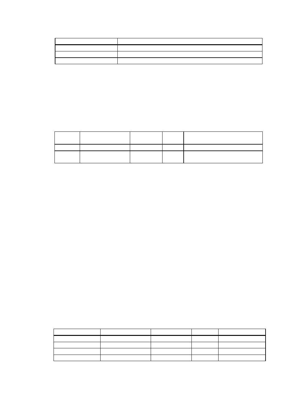
Table 4-1 Error Codes
Error code (word 64)
Description
0
No errors found
1
The instrument doesn't respond
2
Check error (framing or check field error is detected)
4.2 Writing Data to the BASIC Module
The driver allows the CPU to reset accumulated energies and demands in the selected
Powermeter, or synchronously in all Powermeters on line, if this function is supported by the
instruments. The CPU request is transmitted to the BASIC module via the CPU M0 file. The
CPU M0 file structure is shown in Table 4-2.
Table 4-2 CPU M0 file structure
Field No. Field Name
CPU M0 file
word
Range
Description
1
Instrument address
1
0-31
0 = all the instruments
2
Command
2
1-2
1 = Reset accumulated energies
2 = Reset maximum demands
The instrument address value of 0 will apply to all the instruments connected to the BASIC
module.
The command value of 1 will result in resetting the active (+kWh), returned (-kWh) and
reactive (kvarh) energies. The command value of 2 will reset the active power maximum
demand, apparent power maximum demand, and all of the ampere maximum demand values.
The command value of 0 has no action.
4.3 Handshaking Logic
4.3.1 General
Because file integrity is not guaranteed during data transfer via Module files M0 and M1, a
special handshaking logic is applied to avoid the use of data while updating the file.
For handshaking implementation, two least significant bits in word 1 in the CPU output and
input image tables are used. Bit 0 in either cases controls access to the CPU M0 file, and bit 1
controls access to the M1 file. Table 4-3 shows the handshaking bits' assignments and letters
that are used as their designations.
Table 4-3 Handshaking Bits
CPU input word 1
CPU output word 1
Bit designation
CPU File
Function
Bit 1
A
M1
Request to send
Bit 1
B
M1
Clear to send
Bit 0
C
M0
Clear to send
Bit 0
D
M0
Request to send
Here is how handshaking operates.