Caution – S&S Cycle General Flywheel User Manual
Page 6
6.
Using lower oil return hole in cylinder spigots as a
guide, drill
1
⁄
4
" diameter connecting holes in
crankcase to intercept holes drilled
5
⁄
8
" deep in Step
3. See Figure 2 and Picture 5. Driveside crankcase
Drill
1
⁄
4
" diameter hole,
5
⁄
8
" deep
NOTES
●
If base plates are to be used, be sure they are in place.
●
Lower oil return hole in current production S&S
®
cylinders is
1
⁄
2
" on center below base gasket surface of cylinder. This
dimension allows the use of up to 5" stroke using a
1
⁄
8
" thick
base plate. Some early production cylinders have lower oil
hole located about
5
⁄
16
" on center below gasket surface.
These early production cylinders can be used with strokes up
to 4
3
⁄
4
" where base plates are not used.
B.
Clean dirt, filings, etc. out of passageways.
C.
Press a piece of
3
⁄
4
" long x
3
⁄
8
" O.D. steel tubing (Part
93-1032) provided in kit into oil return hole in base
gasket surface until tubing is flush with surface.
Ream hole slightly with drill to remove any burrs that
may exist.
NOTE: A very tight press fit with 100% seal is not critical as tube
will sufficiently divert oil flow to new hole. Loctite
®
may be
applied to tube if fit seems too loose.
5.
Installation Notes
●
When pressing Timken
®
bearings on sprocket shaft, be sure
to lubricate the shaft. If this is not done the bearing may gall
on the shaft and become stuck.
●
Big twin engines using 1958 and later style pinon shafts
may be assembled with any of the different styles of
pinon main bearing sets for 1958 and later engines. If
necessary, bearings can be spaced with thrust washers to
control end play and to insure that rollers run fully within
the bearing race.
●
S&S big twin flywheels can be ordered machined to stock
8
1
⁄
2
" diameter or to small diameter (typically 8
1
⁄
4
"). Small
diameter flywheels are used mainly to provide extra piston
to flywheel clearance thus allowing the use of longer skirted
pistons in long stroke engines. There is also about a 2 pound
difference in weight between stock and small diameter
flywheels. It is important to modify crankcases to accept
flywheels to be used. Flywheels that are too small will leave
a large gap between flywheels and oil scraper resulting in
poor oil scavenging and possible oil consumption problems.
If flywheel diameter is smaller than diameter crankcases
were machined to accept, scraper should be built up to rim
of flywheels. Recommended clearance between flywheels
and scraper is .008" - .010".
●
When sealing crankcase halves, S&S recommends use of high
temp resistant RTV premium silicone sealant or Hylomar
sealant. Use any sealant sparingly to prevent particles of
excess material from entering crankcase and potentially
getting into engine oil.
●
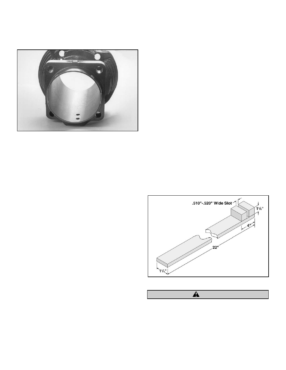
After flywheel assembly is installed in crankcases, rods must be
checked for straightness. S&S Rod Checking Pin, Part 53-0002,
was designed to help perform this procedure. It may also be
necessary, to fabricate a rod bending tool as illustrated in
Figure 3. The purpose of this procedure is to correct for
machining tolerance discrepancies in components which may
lead to pistons not running true in cylinder bores. While rods
may be straight and true, it is sometimes necessary, to bend
them to correct for these machining discrepancies. Do not
bend rod by using tool in wristpin hole as this method may
distort wristpin bushing. We also feel that using a piston in
lieu of a checking pin may prove inaccurate due to variations
in lengths of piston skirts from one side of piston to the other.
Pistons which do not run true in cylinder bores may cause
excessive connecting rod side thrusting. This in turn may lead
to premature ring, piston, connecting rod and rod bearing
wear and eventual failure of these parts.
Picture 5
6
Figure 3
CAUTION