Caution – S&S Cycle General Flywheel User Manual
Page 5
Rod side play will be reduced by about .015" when
crankpin nut is final tightened. Therefore, distance
between flywheel thrust pads as measured in this check
must be .030"-.050" greater than female rod width
measured in step D. For example, if a big twin female
rod measures 1.744", the distance between flywheel
pads must be 1.774"-1.794". If difference between pad
to pad distance and female rod width is less than .030",
female rod must be surface ground on sides to provide
more clearance. Take equal amounts off each side if
more than .010" is to be removed. If more than .050"
must be removed from female rod width or if difference
between pad to pad distance and female rod width is
greater than .050" a different crankpin should be tried.
If side play is incorrect and different crankpins do not
correct problem, contact S&S
®
.
NOTE: S&S recommended rod side play is .015" to .035". If
material is removed from sides of female rod, overall width of
bearing cages must be reduced so bearings and cages are free to
float with rods without contacting flywheel thrust pads. Bearing
cage side clearance of .008 to .020 less than rod width is
recommended.
●
Incorrect connecting rod side play may cause excessive
rod side thrusting and potential damage to rods,
flywheels and other engine components.
●
Connecting rod bearing and cage assemblies that are
wider than female rod may become damaged upon
contact with flywheel thrust pads. Abrasive particles
from damaged rod bearings may circulate in oil and cause
damage to other engine parts.
J.
Finish assembling flywheels and rods. See S&S Flywheel
Assembly Torque Specification table. Check final
connecting rod side play with feeler gauge.
K.
Check flywheel assembly for run out by placing ends of
mainshafts between centers. Place dial indicators on
bearing surfaces of mainshafts. True wheels as needed.
S&S trues flywheel assemblies to .0005" or less runout
on either mainshaft bearing surface. See Picture 4.
NOTE: When truing flywheels, runout measurements must be
taken on mainshaft bearing surfaces. Do not take measurements
on flywheel rims. Flywheel rim will show runout that is not a
valid indication of mainshaft concentricity.
If it is necessary to strike the rim of the flywheels during the
truing procedure, a lead hammer should be used to avoid
damaging the flywheel rim. If rim is dented it may be
impossible to recondition mainshaft tapers due to difficulties
indicating center of taper.
4. Installation
A. For engines of 4
1
⁄
2
" or longer stroke, the oil return holes
in the stock location must be plugged, and the
crankcase must be modified to use the lowered oil
return holes. This modification is necessary due to
increased piston travel in longer stroke engines. Oil
control ring position will be below stock cylinder oil
return hole at the bottom of the stroke. If modification
is not done, oil will be carried to the combustion
chamber by piston rings causing engine to smoke.
NOTE: Engines with strokes shorter then 4
1
⁄
2
" stroke or shorter do
not require this step.
1. If using stock cylinder base gaskets, place base
gasket on cylinder base gasket surface, and punch
1
⁄
4
" hole in gasket directly in center of oil return
hole in base gasket surface of cylinder. S&S gaskets
are pre-punched.
2. Place gasket on driveside crankcase half in its
respective position. Mark crankcase gasket surface
through
1
⁄
4
" diameter hole in gasket.
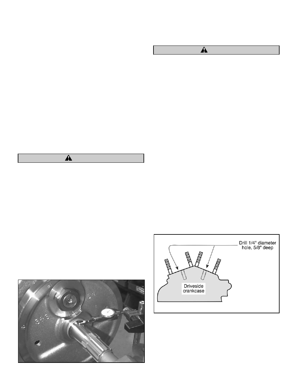
3. Drill
1
⁄
4
" diameter hole perpendicular into crankcase
gasket surface
5
⁄
8
" deep. See Figure 2.
4. Perform Steps 1 through 3 on other cylinder.
5. Bolt the front and rear cylinders on drive side
crankcase half.
CAUTION
Picture 4
CAUTION
Figure 2
5