Caution – S&S Cycle General Flywheel User Manual
Page 3
ASSEMBLY INSTRUCTIONS
1.
Connecting Rod Preparation (All)
NOTE: If S&S
®
connecting rods are used, follow instructions
that accompany rods since rod preparation below has already
been done.
If S&S rods are not used, perform following steps:
A.
To insure adequate oil on sides of rods and matching
thrust surfaces of flywheels, S&S recommends that four
grooves be ground on each side of both front and rear
connecting rods. See Figure 1. Make these grooves
.020" to .030" deep and .030" to .040" wide and should
be ground 90° from each other. After making grooves,
remove all sharp edges and burrs with emery cloth.
B.
With rods assembled on crankpin and bearings, measure
distance between rods at closest points in wristpin holes.
If measurement as shown in Figure 1 exceeds 2.950" for
rods with .792" wrist pins or 2.850" for rods with .892"
wrist pins, grind female rod at points where male rod
makes contact to achieve sufficient clearance.
NOTES
●
Rods clearanced to this dimension provide adequate
clearance for strokes up to and including 5". Do not
remove any more material than is necessary to obtain
required clearance.
●
Use of .892" diameter wrist pins with stock connecting rods
is not recommended.
Inadequate clearance between rods or too much clearancing
on rods will cause unwarranted stress on connecting rods, rod
bearings, pistons, etc. resulting in possible failure of one or all
aforementioned parts.
C.
Thoroughly clean all parts to remove dirt, filings, etc.
Burrs, dirt, filings, etc. left on connecting rod components may
circulate in oil damaging other parts possibly causing engine failure.
2.
Inspect and Clean All Parts
A.
Flywheel type and style can be determined from
coded information in serial number. Check serial
number of flywheels to insure that flywheels are the
correct type and stroke for application. Refer to
flywheel identification information on page 7.
B.
Thoroughly clean all parts to be used. This includes
mainshafts, main bearings, connecting rods, rod bearings,
keys and flywheels including tapers and key ways.
Burrs, dirt, filings, etc. left on flywheel assembly parts may circulate
in oil damaging other parts possibly causing engine failure.
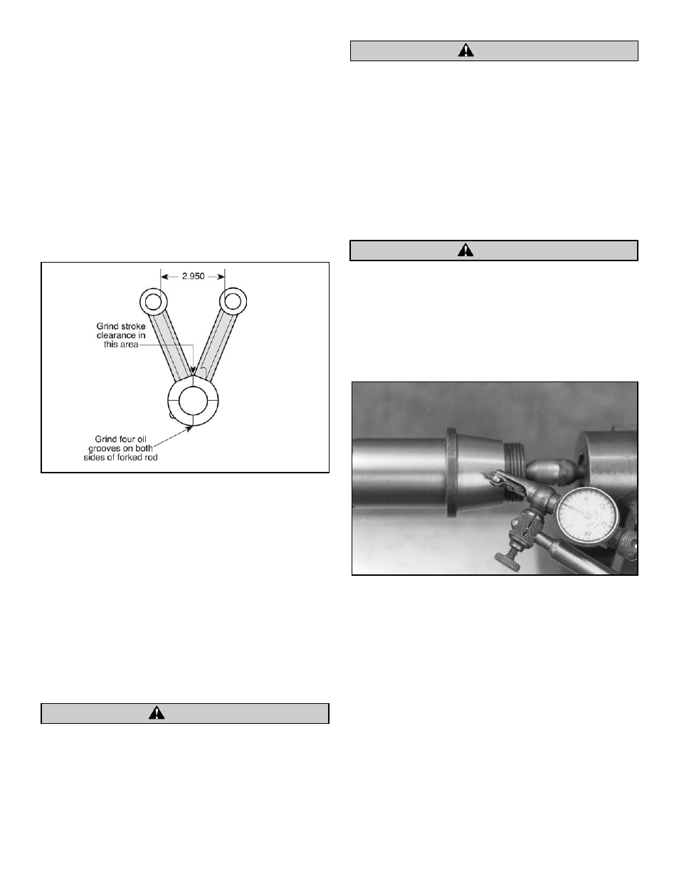
C.
Check both mainshafts between centers for taper
surface to bearing surface concentricity. Make sure
centers on shafts are clean beforehand. If tapers and
bearing surfaces are concentric with each other and
with center, then truing will be easier. See Picture 1.
NOTE: S&S shafts should not require checking as runout on
ground taper and bearing surfaces on S&S shafts is .0003" or less.
D.
Inspect key ways and oil holes in flywheels for burrs.
Remove burrs if necessary.
NOTE: S&S does not recommend lapping tapers to remove burrs.
This practice tends to distort the taper by removing material
unevenly around the circumference. This makes flywheels
difficult if not impossible to true. In addition the lapping process
work hardens the surface of the taper. The resultant hard surface
makes it very difficult to pull shaft or crankpin into taper. If
crankpin and shafts are not pulled fully into flywheel tapers,
excessive rod side play and assembly width may result. Lapped
flywheel tapers are also very difficult to resurface if repairs are
ever needed.
3
CAUTION
Figure 1
CAUTION
Picture 1
CAUTION