Connecting the sample lines to the model gd-k11d, Wiring the model gd-k11d – RKI Instruments GD-K11D User Manual
Page 13
Model GD-K11D Operator’s Manual
Installation • 9
2. Use two screws through the slot cutouts at the top of the housing to secure the
housing to a vertical surface at the mounting site (see Figure 2.)
3. Use two screws through the mounting holes at the bottom of the housing to support
the installation of the Model GD-K11D (see Figure 2.)
Connecting the Sample Lines to the Model GD-K11D
1. Attach 4 x 6 mm PTFE teflon tubing to the gas in fitting. Place the opposite end of the
tubing at the sampling area.
CAUTION:
Avoid loops or slumps in the incoming sample line. To reduce response time, keep the
incoming sample line as short as possible.
2. Attach 4 x 6 mm PTFE teflon tubing to the gas out fitting. Route the opposite end of
the tubing to an open area where the sample can safely disperse.
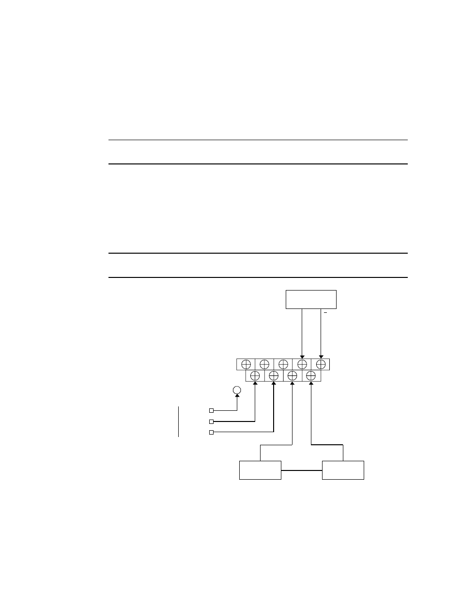
Wiring the Model GD-K11D
This section describes procedures to connect AC power to the Model GD-K11D. This
section also describes
optional
procedures to connect a controller or recorder and external
alarm device to the Model GD-K11D. Figure 3 illustrates wiring connections to the
Model GD-K11D.
WARNING: Always verify that the Model GD-K11D’s power switch is in the OFF
position before you make wiring connections to the Model GD-K11D.
Figure 3: Wiring the Model GD-K11D
AC POWER
115V, 60 HZ.
GROUND
NEUTRAL
HOT
E
ALARM
DEVICE
CONTROLLER/
RECORDER
+
4-20
mA
output
POWER
SOURCE
CAUTION: If the alarm device draws more than 1 amp, use the
alarm contacts to control a relay with an appropriate contact rating.