RKI Instruments GD-K11D User Manual
Page 10
6 • Description
Model GD-K11D Operator’s Manual
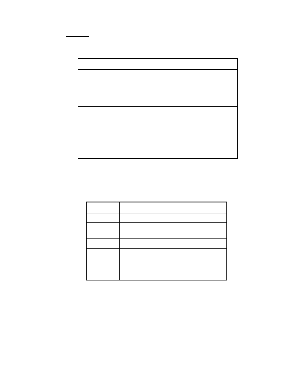
Status lights
The display board includes five status lights. Table 3 lists each light and its function.
Program buttons
The display board includes five buttons. The MODE,
∆
(PEAK),
∇
, and SET (AL.P)
buttons are directly below the display screen. The TEST button is the red button near the
bottom right of the display board. Table 4 lists each button and its function.
Table 3: Model GD-K11D Status Lights
Light
Status
PW/TR
(power)
• live power is connected to GD-K11D and the
power switch is ON (solid light)
• fail condition (flashing light)
AL
(alarm)
• gas alarm condition (solid light)
• over range condition (solid light)
ZERO
• GD-K11D is prepared for adjustment of zero
setting (flashing light)
• GD-K11D accepted zero setting (solid light)
SPAN
• GD-K11D is prepared for adjustment of span
setting (flashing light)
• GD-K11D accepted span setting (solid light)
SKIP
GD-11D is in maintenance mode (flashing light)
Table 4: Model GD-K11D Program Buttons
Button
Function
MODE
Enters maintenance mode
∆
(PEAK)
• Increases/changes the setting on the display
• Displays the peak reading
∇
Decreases/changes the setting on the display
SET (AL.P)
• Prepares a setting to be changed
• Enters a new setting
• Displays the alarm point
TEST
Enters alarm test mode