Control pcb – RKI Instruments M2A User Manual
Page 17
M2A Transmitter Operator’s Manual
12
Relay Terminal Strips
The right column of terminal strips consists of, from top to bottom, the fail, alarm 1, and alarm 2
relay terminal strips. They are three-position plug-in style terminal strips. The relay terminal strips
are used to connect devices such as lights and horns that are controlled by the relay contacts. The
relay contacts are rated at 115 VAC, 5 amps. The relay contacts may also be used to control higher
rated relays.
Termination Jumper
A two pin header with a termination jumper installed is located below the Modbus terminal strip.
Leave this jumper installed unless directed to remove it for a Modbus installation. See “Chapter 8:
RS-485 Modbus Output” on page 51 for a description of using the M2A in a Modbus system.
Ground Jumper
A two pin header with a jumper installed is located along the left side of the terminal PCB. Leave
this jumper installed unless directed to remove it for a Modbus installation. See “Chapter 8: RS-485
Modbus Output” on page 51 for a description of using the M2A in a Modbus system.
Control PCB
The OLED display and control switches are located on the control PCB. It is installed on top of the
terminal PCB by lining up its three spacing standoffs with the banana jacks in the terminal PCB
mounting standoffs and pushing it onto the banana jacks. The jacks retain the control PCB.
OLED Display
The OLED display is located at the top of the control PCB. It indicates the current gas reading and
displays messages and parameters in the M2A’s programs.
Control Buttons
The M2A includes three push button switches that allow you to enter the M2A’s operating modes,
navigate through the modes, update settings, and save changes to the settings. The push button
switches are located along the bottom edge of the control PCB (see Figure 9). The UP/YES button
is on the left, the DOWN/NO button is in the middle, and the ENTER button is on the right.
Just above each push button switch is a magnetic switch with the same function as the push button
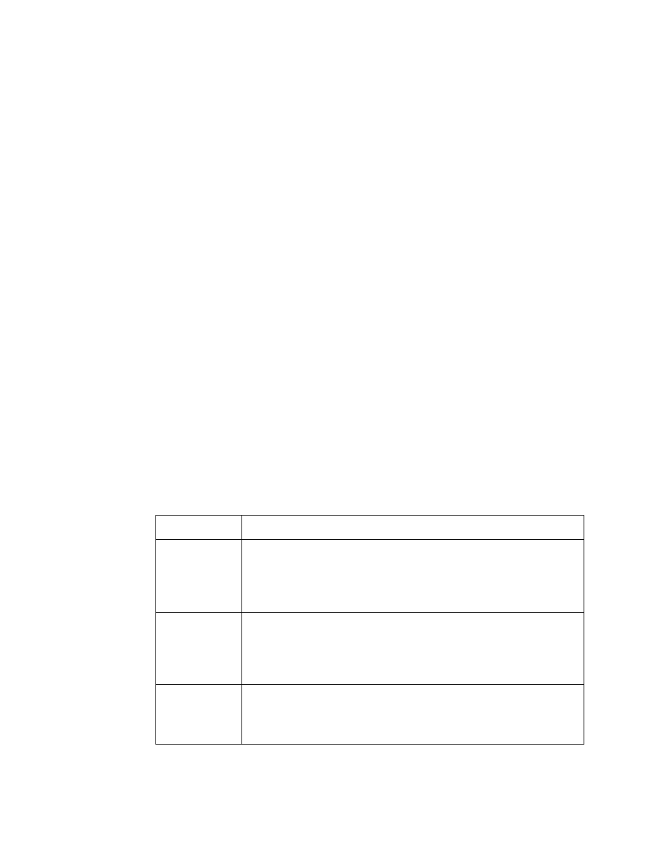
Table 3: M2A Control Button Functions
Switch
Function
UP (YES)
•
Saves settings
•
Changes the displayed setting
•
Enters the Calibration Program
•
Enters Gas Type Mode (press with DOWN/NO button)
•
Enters Configuration Mode (press with ENTER button)
DOWN (NO)
•
Cancels setting changes
•
Changes the displayed setting
•
Enters Gas Type Mode (press with UP/YES button)
•
Enters Modbus Mode (press with ENTER button)
•
Displays the Information Screen
ENTER
•
Initiates operations
•
Enters Configuration Mode (press with UP/YES button)
•
Enters Modbus Mode (press with DOWN/NO button)
•
Functions as an alarm reset switch