Chapter 3: operation, Normal operation, Alarm indications – RKI Instruments Pioneer 16R User Manual
Page 11
Chapter 3: Operation
Normal Operation
Normal operation is defined as follows:
•
The start-up procedure is complete.
•
The Pioneer is not indicating an alarm 1, alarm 2, alarm 3, or fail condition.
•
The Pioneer is not running the Instrument Setup, Channel Setup, Calibrate, or Display Setpoints and
Readings program.
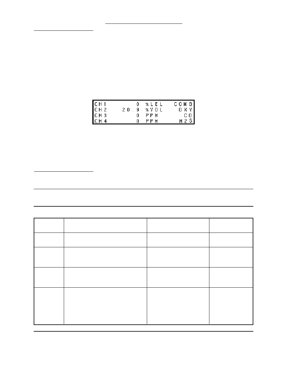
During normal operation, the Pioneer simultaneously displays the target gas, unit of measure, and current
gas reading for all active channels. The Pioneer displays the readings horizontally for each channel. Four
channels are displayed on each of the four displays visible through the front panel. On each display the
channel sequence starts at the top and goes down. For example, on the upper left display, channel 1 is
the top reading and channel 4 is the bottom reading.
The PILOT light on the front panel, the POWER light on the main circuit board, and the pilot light on each
analyzer card are on during normal operation indicating that the monitor and analyzer cards are receiving
incoming power. The output at terminals 8 and 9 of the analyzer card’s output terminal strip is 4 to 20 mA or
0 to 1 V and is proportional to the detection range of the detector that is wired to the analyzer card. (The
standard output at terminals 8 and 9 is 4 to 20 mA.)
Alarm Indications
This section describes the Pioneer in alarm 1, alarm 2, alarm 3, and fail conditions and suggests response
to these conditions. Table 3-1 lists the alarm indications for each condition.
N O T E
:The Pioneer includes alarm on and alarm off delay settings. The alarm indications described in this
section operate according to the default delay settings. See the Channel Setup program section
in the applicable detection insert to display or change the alarm on and alarm off delay settings.
TABLE 3-1: Visual and Audible Alarm Indications
Condition
Cause
Visual Indication
Audible
Indication
Alarm 1
Increasing (or decreasing for O2) gas
reading at or above alarm 1 setpoint
• ALARM 1 light is on
• Gas reading flashes
Pulsing tone
Alarm 2
Increasing (or decreasing for O2) gas
reading at or above alarm 2 setpoint
• ALARM 1 and ALARM 2
lights are on
• Gas reading flashes
Faster pulsing
tone than Alarm 1
Alarm 3
Increasing gas reading at or above
alarm 3 setpoint
• ALARM 1, ALARM 2 and
ALARM 3 lights are on*
• Gas reading flashes
Faster pulsing
tone than Alarm 2
Fail
• Disconnected or misconnected
detector wiring
• Disconnected or misconnected
analyzer card
• Display reading below fail setpoint
• Defective components
• Fail light is on
Steady tone
* T
he ALARM 1 and ALARM 2 lights are not on for oxygen channels
N O T E
:You can select normally energized or normally de-energized relays in the Channel Setup program.
The following sections describe the default setting for the relays: normally de-energized. The fail
Pioneer-R16 Operator’s Manual
Operation
10