Overview, Back panel, Chapter 2: description – RKI Instruments SM-2003U User Manual
Page 9: Power switch
Overview • 9
Chapter 2: Description
Overview
This section describes the SM-2001U and SM-2003U single module
calibration stations. They are designed to be used on a table top and
consist of the back panel, control panel, status LEDs, USB port, and
instrument connections.
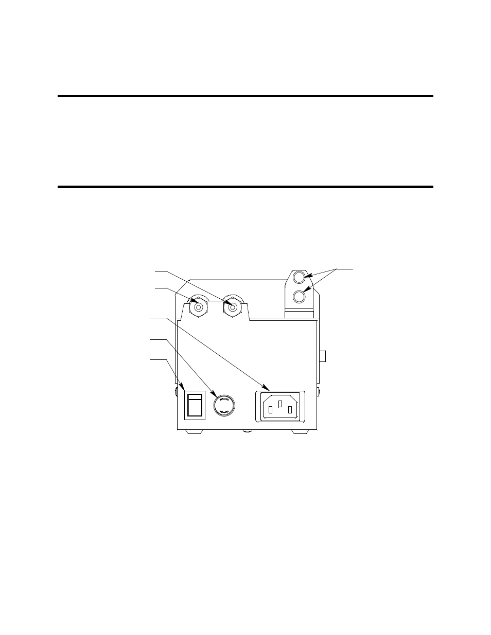
Back Panel
The back panels of both types of calibration stations are identical. The
back panel is shown in Figure 1 below. It includes the power switch, fuse,
power cord plug, sample fittings, and air filter.
Power Switch
The power switch is a rocker switch located in the lower left corner of the
back panel. The calibration station is on when the upper half of the
switch, the “1” position”, is pressed in, and off when the lower half of the
switch, the “0” position, is pressed in.
Exhaust Fittings
AIR Fitting
CAL. GAS Fitting
2A
l
O
AC Power Cord Plug
Power Switch
Fuse
Figure 1: SM-2001U & SM-2003U back panel