Control panel, status leds & usb port, Mode rotary switch, Figure 2: control panel & status leds – RKI Instruments SM-2003U User Manual
Page 11: Control panel, status leds & usb port • 11
Control Panel, Status LEDs & USB Port • 11
Control Panel, Status LEDs & USB Port
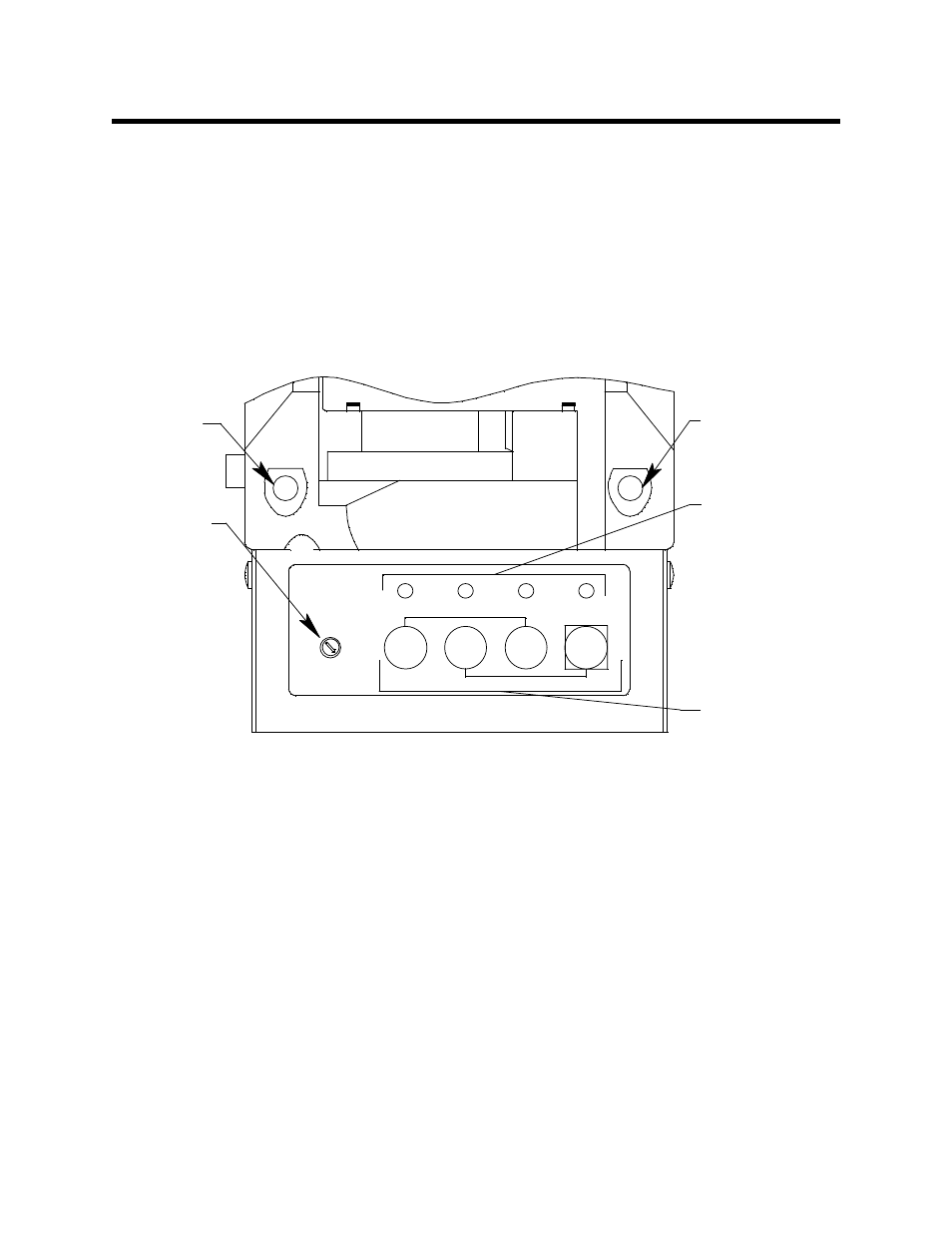
The control panel and status LEDs are the same for both types of
calibration stations. The control panel is used to setup and operate the
calibration stations. It is located at the front of the calibration stations. It
includes the MODE rotary switch, control buttons, and the control button
LEDs. The CAL. and CHARGE status LEDs are located on the top front
of the calibration stations.
MODE Rotary Switch
The MODE rotary switch is located on the left end of the control panel. It
is a 10 position rotary switch whose positions are labelled 0 -9. Each
position defines the value of various bump test parameters. See “Setting
the MODE Switch” on page 18 for a complete description of the
parameters and settings.
Control
LEDs
9
MODE
Mode
Switch
CAL.
Status
LED
CHARGE
Status
LED
Control
Buttons
2
3
1
4
0
5
6
7
8
BUMP
CAL.
VOL.
COPY
CLEAR
OFF
CAL.
CHARGE
Figure 2: Control Panel & Status LEDs