Glass bead, Connector receptacle – Northern Connectors Radiall SMA Series Coaxial Connectors User Manual
Page 31
www.radiall.com
8-31
SMA
FIElD REPlaCEaBlE HERMETIC MICROSTRIP
RECEPTaClE INFORMaTION
The RADIALL panel drilling on page 8-27 recommends an additional bore or chamfer machining on the outer edge
of the glass bead housing. This additional machining allows to place a pre-form (solder stick Dia. 0.3 mm) before soldering.
After mounting, solder is flushing and allows the right positionning of the receptacle.
The EMI gasket efficiency is guaranteed.
glaSS BEaD aND CONNECTOR aSSEMBlY
INTO THE MICRO ElECTRONIC PaCKagE
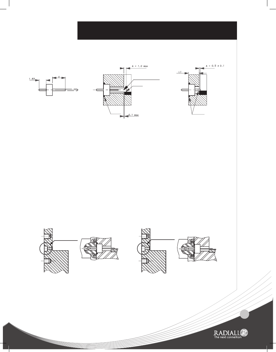
glaSS BEaD MOUNTINg
Version without
BAD
Version with additional machining
RIGHT
solder
solder
removable socket
solder
V
A
+
1
L
=
X
5
.
0
±
0
.
2
=
X
n
o
it
p
o
t
e
k
c
o
s
t
u
o
h
ti
w
n
o
it
p
o
t
e
k
c
o
s
h
ti
w
glaSS BEaD
1 Adjust X by cutting the pin if necessary.
2 Introduce the glass bead into its cavity.
3 Place a ring of solder in the groove around the glass bead (a 0.3 mm wire dia. of solder is recommended).
4 Solder the pin (or optional socket) on the PCB trace inside the package.
Beware there is not too much welding.
IMPORTaNT:
For maximum RF performances, the link track/pin must be as thin as possible.
We advise therefore to follow the A dimension rigorously, by soldering accurately the pin or the socket directly on the trace.
CONNECTOR RECEPTaClE
Place the ”EMI” screening gasket in the groove of the receptacle (if applicable).
Introduce gently the receptacle on the glass bead pin, then screw the flange (use the appropriated tool for screw-in
receptacle).