Hpha36c5h trowel — maintenance – Multiquip HPHA36C5H User Manual
Page 32
PAGE 32 — HPHA36C5H WALK-BEHIND TROWEL— OPERATION AND PARTS MANUAL — REV. #3 (07/06/10
)
Trowel Arm Adjustment
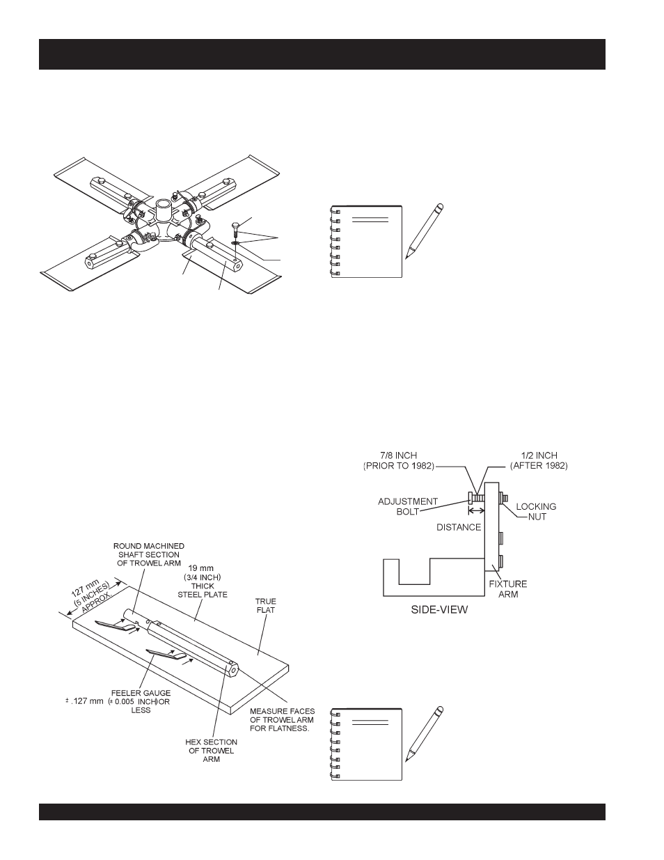
Shown in (Figure 45) is the adjustment fixture with a trowel arm
inserted. As each trowel arm is locked into the fixture, the arm bolt
is adjusted to where it contacts a stop on the fixture. This will
consistently adjust all of the trowel arms, keeping the finisher as
flat and evenly pitched as possible.
1. Locate the trowel arm adjustment tool P/N 1817. Check the
adjusting bolt/fixture arm distance is correct for your trowel.
Adjust to specifications shown in Figure 45.
Figure 45. Trowel Arm Adjustment Tool Side View
Trowel Arm Flatness Test
1. Using a piece of 3/4 inch thick steel plate or any surface which
is
true
and
flat
, check all
faces
of each trowel arm for flatness.
2. Check the blade-mounting sides of the trowel arm (hex
section only) using a ten thousands of an inch (max.) feeler
gauge (Figure 44) between the flat of the trowel arm and an
extremely flat
test surface.
3. If the trowel arm is found to be
uneven
or
bent
, replace the
trowel arm. A bent trowel arm will not allow the trowel to
operate in a smooth fluid rotation.
4. Next, check each of the six sides of the round machined shaft
section of the trowel arm. Each section should have the
same
clearance
between the round of the trowel arm shaft and the
test surface.
Figure 44. Trowel Arm Flatness Test
HPHA36C5H TROWEL — MAINTENANCE
Trowel Blade Removal
1. Remove the trowel blades from the trowel arm by removing
the three hex head bolts (Figure 43) from the trowel arm. Set
blades aside.
Figure 43. Trowel Blades
2.
Wire brush
any build-up of concrete from all six sides of the
trowel arm. Repeat this for the remaining three arms.
NOTE
Trowel arms can be damaged by
rough handling or by striking
exposed plumbing or forms while in
operation.
ALWAYS look-out for
objects which might cause damage
to the trowel arms.
REMOVE
LOCK
WASHER
HEX
HEAD
BOLT
BLADE
ARM
NOTE
Arms with CLOCK-WISE blade
rotation use the fixture arm in the
UP position (A in Figure 46). Arms
with COUNTER CLOCK-WISE
blade rotation use the fixture with the
fixture arm in the DOWN position.
(B in Figure 46).
2. Ensure the fixture arm is in the proper setting (up or down) for
your trowel arm rotation as shown in Figure 46.