Hpha36c5h trowel — assembly and installation – Multiquip HPHA36C5H User Manual
Page 20
PAGE 20 — HPHA36C5H WALK-BEHIND TROWEL— OPERATION AND PARTS MANUAL — REV. #3 (07/06/10
)
2.
Lock the spring in the compressed position, by releasing
the blade pitch adjustment trigger, (Quick-Pitch™ model).
3.
Remove one brass set nut from the blade pitch cable end
as shown in (Figure 13).
4.
Thread the second brass set nut towards the cable as far
as possible.
HPHA36C5H TROWEL — ASSEMBLY AND INSTALLATION
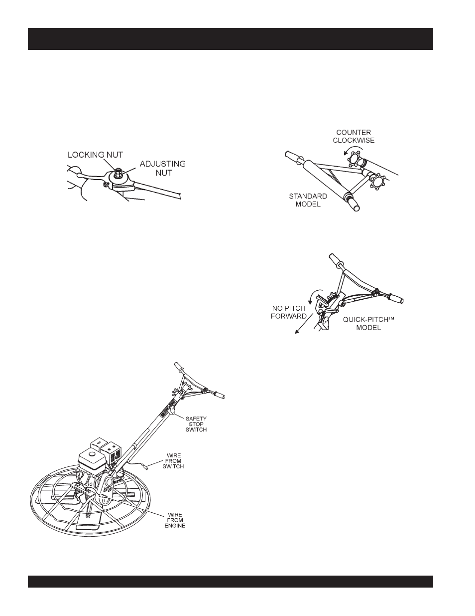
Safety Stop Switch Wire
Locate the
safety stop switch wire
protruding from the handle
tube (Figure10) and connect it to the
tail wire
on the engine.
Test the safety stop switch to insure proper operation.
Figure 10. Engine Safety Stop Wire Connection
Figure 11. "No Pitch" Position (Standard)
Figure 12. "No Pitch" Position (Quick-Pitch™)
1.
Expose the pitch cable to maximum by adjusting the handle
pitch to the "no pitch" position. On the standard model turn
the pitch control counter-clockwise, (Figure 11). On the
Quick-Pitch™ model, pivot the pitch handle forward or no
pitch, (Figure 12).
7. These are general instructions. Installation of the throttle
cable may vary for different engine configurations. Please
look for more detailed instructions inside the box containing
the handle. These more detailed instructions should provide
adequate guidance for installation.
4.
Tighten cable clamp screw and swivel stop screw.
5.
After the cable has been installed on the engine, adjust
and tighten operator position of the handle to lock the
throttle cable at the proper length.
6.
Adjust cable tension loosening the lock nut on the throttle
cable receiver (Figure 9), loosening or tightening the
adjuster nut below it, then retightening the lock nut.
Pitch Cable Installation
Figure 9. Throttle Adjust