Maintenance – Multiquip HHXG5 User Manual
Page 40
page 40 — HHXg5 RIDe-ON TROWeL • OpeRaTION maNuaL — Rev. #1 (10/25/10)
Maintenance
2. Loosen the jam nut and cone point square head set screw.
3. Carefully lift the upper trowel assembly off of the spider
assembly. A slight tap with a rubber mallet may be
necessary to dislodge the spider from the main shaft
of the gearbox.
Trowel Blade Removal
Remove the trowel blades by removing the three hex head
bolts (Figure 38) from the trowel arm. Set blades aside.
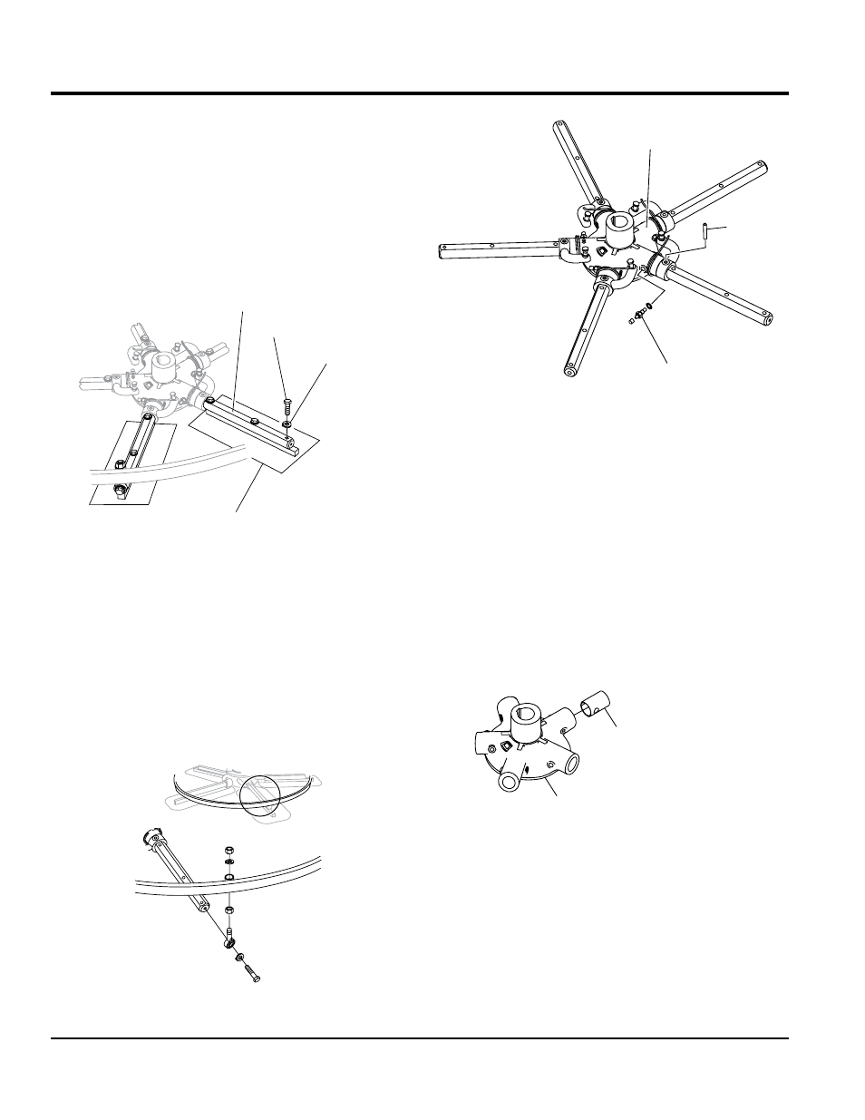
Figure 38. Trowel Blades
Trowel arm Removal
1. Remove the hardware securing the stabilizer ring to
the trowel arm. (Figure 39)
2. Each trowel arm is held in place at the spider plate
by a hex head bolt (zerk grease fitting) and a roll pin.
Remove both the hex head bolt and the roll pin (Figure
35) from the spider plate.
3. Remove the trowel arm from the spider plate.
Figure 39. Stabilizer Ring
Trowel Arm
Lock Washer
Trowel Blade
Hex Head Bolt
Figure 40. Removing Roll Pin and Grease Zerk
Fitting
4. Should the trowel arm inserts (bronze bushing) come
out with the trowel arm, remove the bushing from the
trowel arm and set aside in a safe place. If the bushing
is retained inside the spider plate, carefully remove
the bushing.
5. Examine the bronze trowel arm bushing (Figure 41),
and clean if necessary. Replace bushing if out-of-
round or worn.
Figure 41. Bronze Bushings
6. Wire brush any build-up of concrete from all six sides
of the trowel arm. Repeat this for the remaining arms.
Spider Plate
Roll Pin
Hex Head Bolt
(Zerk Fitting)
Spider Plate
Bronze Bushing