Controls and indicators – Multiquip HHXG5 User Manual
Page 18
page 18 — HHXg5 RIDe-ON TROWeL • OpeRaTION maNuaL — Rev. #1 (10/25/10)
cOntrOlS anD inDicatOrS
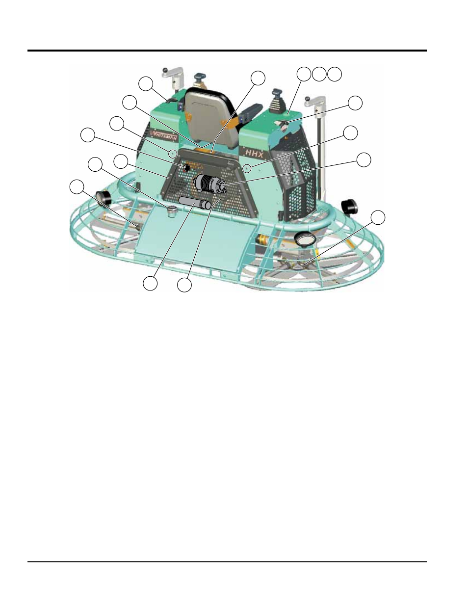
Figure 3. HHXG5 Controls and Indicators (Rear)
17
18
19
19
35
35
29
21
22
28
24
30
23
20
25 26 27
17.
Rear guard — Remove to access right side of
engine and internal components for service and
maintenance.
18.
Safety-Stop Switch — Shuts down engine when
operator is not sitting in seat .
19.
Lift points — Located on both the left and right sides
of the main frame. Used when the trowel must be lifted
onto a concrete slab.
20.
Right-Side Spider — Consists (basic) of trowel arms,
blades, wear plate, and thrust collar etc.
21.
Left-Side Spider — Consists (basic) of trowel arms,
blades, wear plate, and thrust collar etc.
22.
Fuel Filler Cap — Remove this cap to add fuel.
23.
engine Dip Stick — Indicates engine oil level. Add
oil as required.
24.
Oil Filter — Provides oil filtering for the engine.
25.
Oil Indicator Light — Lights red when oil pressure
is low.
26.
Water Temperature Light — Lights red when water
temperature is high.
27.
Charge Indicator — Lights red when electrical system
is not charging properly.
28.
exhaust Outlet — Exhaust gases routed through
muffler and out the back of the rear guard.
29.
air Filter assembly — Helps prevent dirt and debris
from entering the fuel system. Lift Locking Latch on
cannister to gain access to filter element.
30.
Document Box — Use to hold and protect Operation
Manual.