Startup/operation, Engine startup, Operation – Multiquip MQ62TDD User Manual
Page 25: Figure 13. ignition switch, Figure 12. engine speed control lever, Figure 14. engine status indicators lamps
MQ62TDD TRASH PUMP • OPERATION AND PARTS MANUAL — REV. #0 (07/30/09) — PAGE 25
ENGINE STARTUP
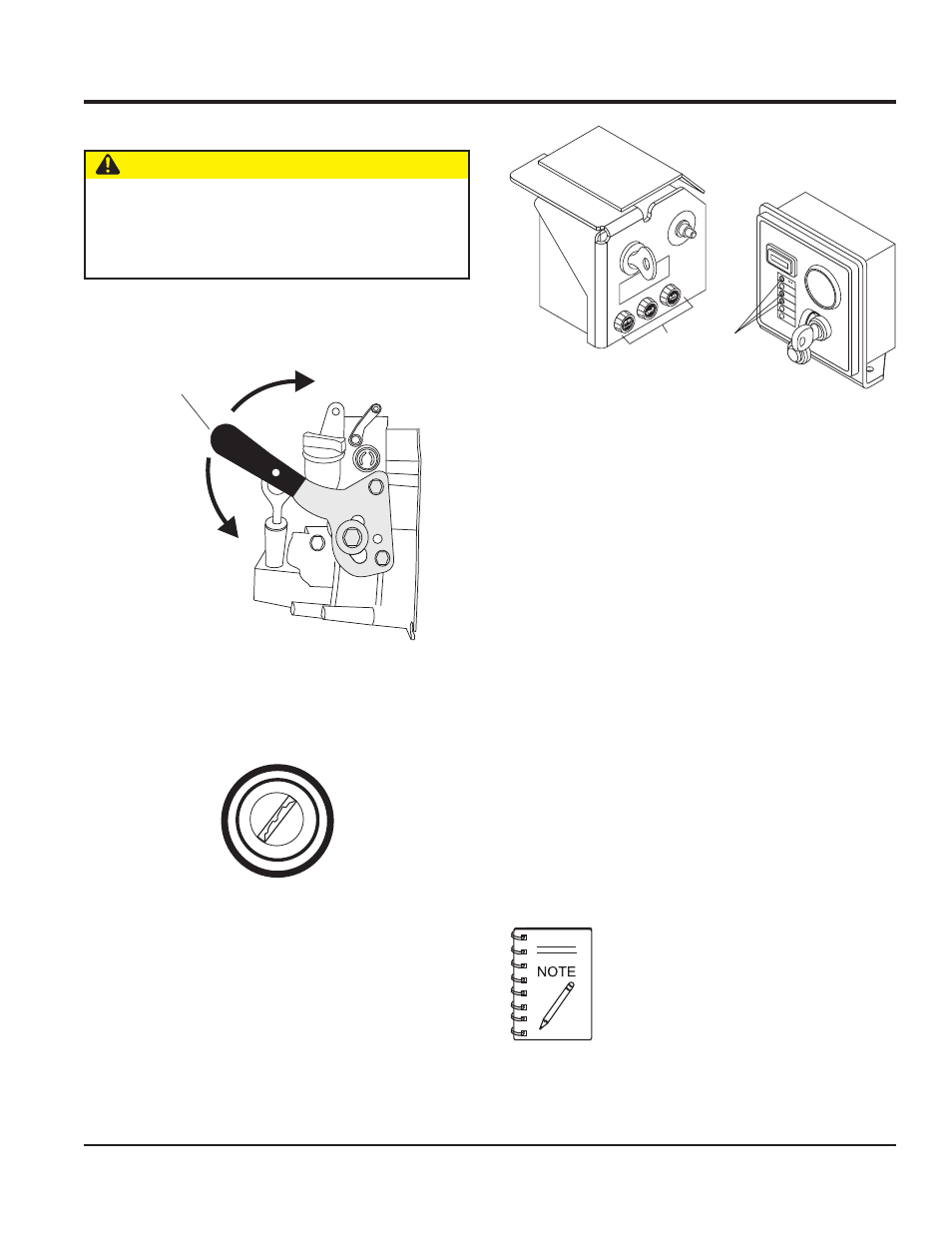
1. Set the
Engine Speed Control Lever (Figure 12) to a
position half way between start and stop.
2. Insert ignition key into ignition switch (Figure 13), turn
ignition key clockwise to position I, and verify that all
three status indicator lights (Figure 14) are ON.
3. Continue turning ignition key through positions II and
III while pushing the red button at the same time.
4. Release ignition key and red button as soon as engine
fully starts, and verify that ignition key automatically
returns back to position I. Verify that all three lamp/
LED status indicator lights are OFF when the engine
is started.
STARTUP/OPERATION
8. If charge lamp or LED remains lit, increase engine
speed until lamp/LED goes off. When the charge
indicator lamp/LED goes off, it can then be assumed
that the charging system is working correctly.
9. If the charge lamp or LED remains on while the engine is
running, refer to Table 12 (Engine Troubleshooting) or the
Deutz Engine Repair Manual.
10. Move
speed control lever to full speed position for
maximum engine speed. (See Figure 12)
OPERATION
1. The pump should begin pumping water within a minute
depending on the length of suction hose and height
the pump is above water.
2. If pump does not begin to pump water after a few
minutes, check for loose connections or air leaks in
suction hose. Make sure there is water in the pump
end and strainer is not clogged with debris, reference
Table 11 (Pump Troubleshooting).
0
P
I
II
III
Figure 13. Ignition Switch
Longer suction hoses will require more time
for the pump to begin pumping water.
CAUTION — Equipment Damage Hazards
DO NOT attempt to start the engine unless the pump
has previously been
primed with water. Severe
damage to the pump's mechanical seal will occur if
pump has not been primed.
Figure 12. Engine Speed Control Lever
STOP
ENGINE SPEED
CONTROL
LEVER
FULL THROTTLE
(RUN POSITION)
Figure 14. Engine Status Indicators Lamps
NOTICE
RED
BUTT
ON
MUST
BE
DEPRESSED
FOR
ENGINE
ST
AR
T
UP
AU
X
1
AU
X
2
OF
F
RU
N
HOU
RS
ST
ART
FU
SE
LO
CA
TE
D
IN
SIDE
PANE
L
LED
STATUS
INDICATORS
LAMP
STATUS
INDICATORS