Maintenance – Multiquip MRH800DS2 User Manual
Page 30
PAGE 30 — MRH800DS2 VIBRATORY ROLLER • OPERATION AND PARTS MANUAL — REV. #1 (04/12/11)
MACHINE MAINTENANCE
1. At the end of each day’s operation, wash down dust
and dirt off the machine. Clean area around drums ad
scrapers making sure all mud is removed.
2. Drain water tank completely.
3. Cover the machine to prevent dust and store in dry
place away from sun exposure.
LONG TERM STORAGE
1. Conduct thorough lubrication and oil change.
2. Disconnect battery terminals and dismount battery
from machine. Store battery.
3. If there a possibility that ambient temperature will drop
below freezing point, add antifreeze agent to coolant.
4. Cover the inlet and outlet of air cleaner and muffl er
securely.
5. Store machine indoors. Do not leave outdoors.
6. Refer to Table 8 for lubrication necessary for the
machine.
BATTERY MAINTENANCE
1. Use a fl ashlight to check battery electrolyte level.
Always check that the engine is stopped.
2. If a battery has not been used for some time, reduce
the charge level initially to protect each plate inside
the battery.
3. Check the battery terminals periodically to ensure that
they are in good condition.
4. Use wire brush or sand paper to clean the battery
terminals.
5. Check battery for cracks or any other damage. If
white pattern appears inside the battery or paste has
accumulated at the bottom, replace the battery.
6. Measure the specifi c gravity of electrolyte:
NOTICE
Read and understand the battery safety information in
the front of this manual before performing maintenance
on the battery.
MAINTENANCE
• completely charged: 1.270 - 1.290
• needs charging: 1.260 or lower.
7. If the machine will not be in operation for a long period
of time, charge the battery suffi ciently, tighten all caps
correctly, store in cool dry place and check the battery
charge level every month to maintain the performance
of the battery.
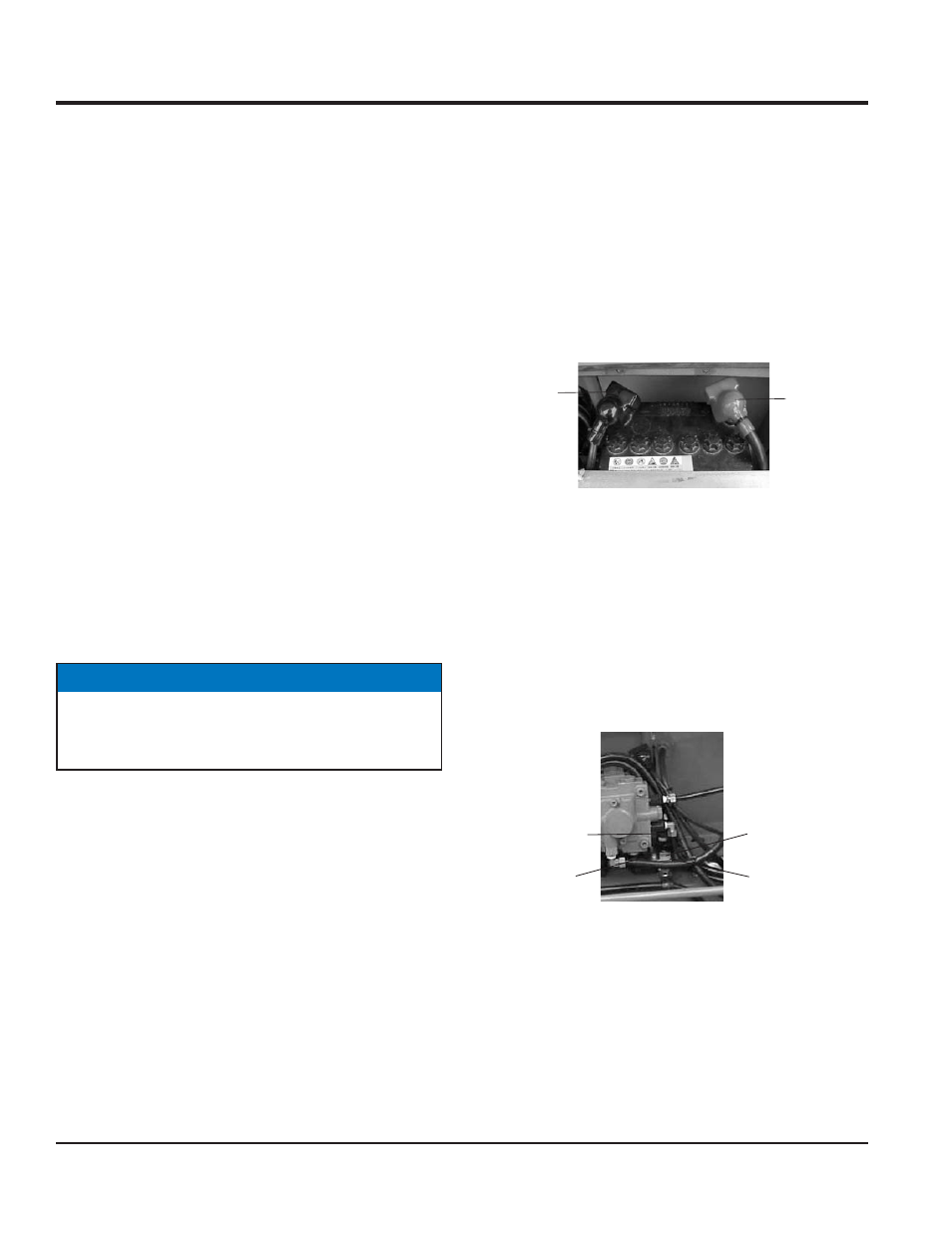
BATTERY CABLE CONNECTION
1. When removing cable, disconnect the ground side
(normally negative) fi rst (Figure 23).
Figure 23. Battery Connection
FORWARD AND REVERSE TRAVEL ADJUSTMENT
2. If neutral position for forward and reverse travel has
been displaced, conduct the neutral adjustment.
3. If roller travels forward with the ball of ball plunger
remaining in V slot of the guide, loosen M8 bolt and
slide the slide plate slightly toward the engine. If the
roller travels backward, slide the plate towards side
plate (Figure 24).
Figure 24. Adjustment of Neutral Position
4. When installing cable, connect the ground side
(normally negative) last.
5. With M8 bolt tightened, start engine and check the
neutral for forward and reverse. If still displaced, repeat
the procedure.
6. If neutral position of forward/reverse lever has been
displaced, use the turn buckle located on the oil pump
side of forward/reverse cable.
NEGATIVE
TERMINAL
POSITIVE
TERMINAL
PLUNGER
GUIDE
SIDE PLATE
M8 BOLT