MTS Series 252 Servovalves User Manual
Page 26
Series 252 Servovalve Product Information
26
252 Servovalve Installation
Installation
Servovalve Locating Pin
Note
For mounting the Model 252.2x and 252.4x servovalves use four 5/16-18
x 1-1/2 in. ASTM A574 socket head cap screws and the Model 252.3x
servovalve uses four 3/8-16 x 1-3/4 in. ASTM A574 socket head cap
screws. As the screws are successively tightened, those previously
tightened will lose clamping force. Continue tightening until all screws
are at the specified torque.
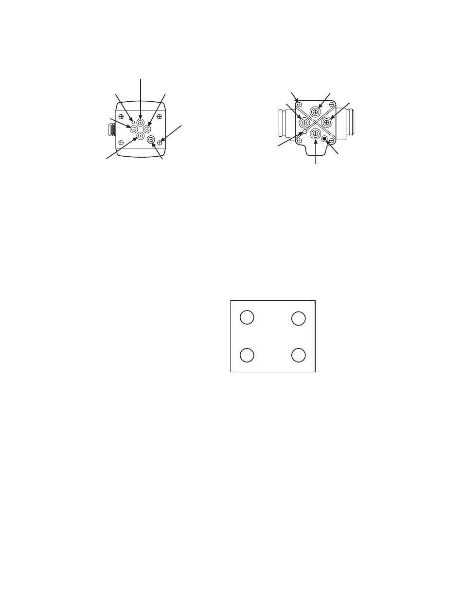
5. After lubricating the mounting screws with a light film of oil, tighten each
one until it is firmly seated. Using the sequence shown, tighten the socket
head screws to 5 lbf·ft.
•
Continue using the pattern and tighten the socket head screws to a final
torque of 13-19 lbf·ft for 252.2x and 252.4x servovalves.
•
Continue using the pattern and tighten the socket head screws to a final
torque of 23-34 lbf·ft torque for 252.3X servovalves.
Note
For manifolds machined with metric threads, the requirements are as
follows:
252.2X and 252.4X Servovalves: M8 x 1.25 mm x 40 mm long socket
head cap screws (DIN 912 Class 12.9). Final torque 19-28 N·m.
252.3X Servovalves: M10 x 1.5 mm x 45 mm long (DIN Class 12.9. Final
torque 36-53 N·m.
6. Connect the four-pin electrical cable from the controller to the servovalve.
7. Turn on electrical and hydraulic system power.
Locating Pin
Pressure
Port
Control Port No. 2
Mounting Holes
(4 Places)
Return Port
Control Port
No. 1
Pilot Pressure Port
(optional)
Control Port
No. 2
Auxiliary Pilot
Pressure Port
Locating Pin
Control Port No. 1
Mounting Holes
(4 places)
Return Port
Pressure Port
1
2
3
4