Series 293.1x hsm controls and indicators – MTS Hydraulic Service Manifold Model 293-12B User Manual
Page 43
Series 293.1X HSM Controls and Indicators
Model 293.1X HSM Controls and Indicators
Description
Item
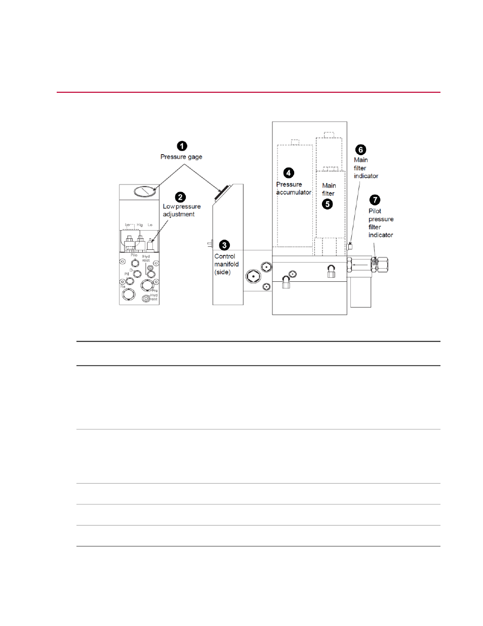
Pressure Gage
1
A liquid-filled, constant-read pressure gage is connected directly to the output pressure line.
A small orifice protects it against damage from rapid pressure changes. For single-channel
operation, the pressure gage is located on the main manifold. For multichannel operation,
each control manifold contains a pressure gage.
Low-Pressure Adjustment
2
A variable orifice is used to set the output pressure of the HSM in the low-pressure mode.
For single-channel operation, the low-pressure adjustment is located on the main manifold.
For multichannel operation, each control manifold contains a low-pressure adjustment.
Control Manifold (side)
3
Pressure Accumulator
4
Main Filter
5
Series 293 Hydraulic Service Manifold Product Information | 43
Operation