System checks – MTS Model 293-32 Hydraulic Service Manifold User Manual
Page 39
Description
Item
Low Pressure Adjustment
5
Low Pressure Solenoid
6
High Pressure Solenoid
7
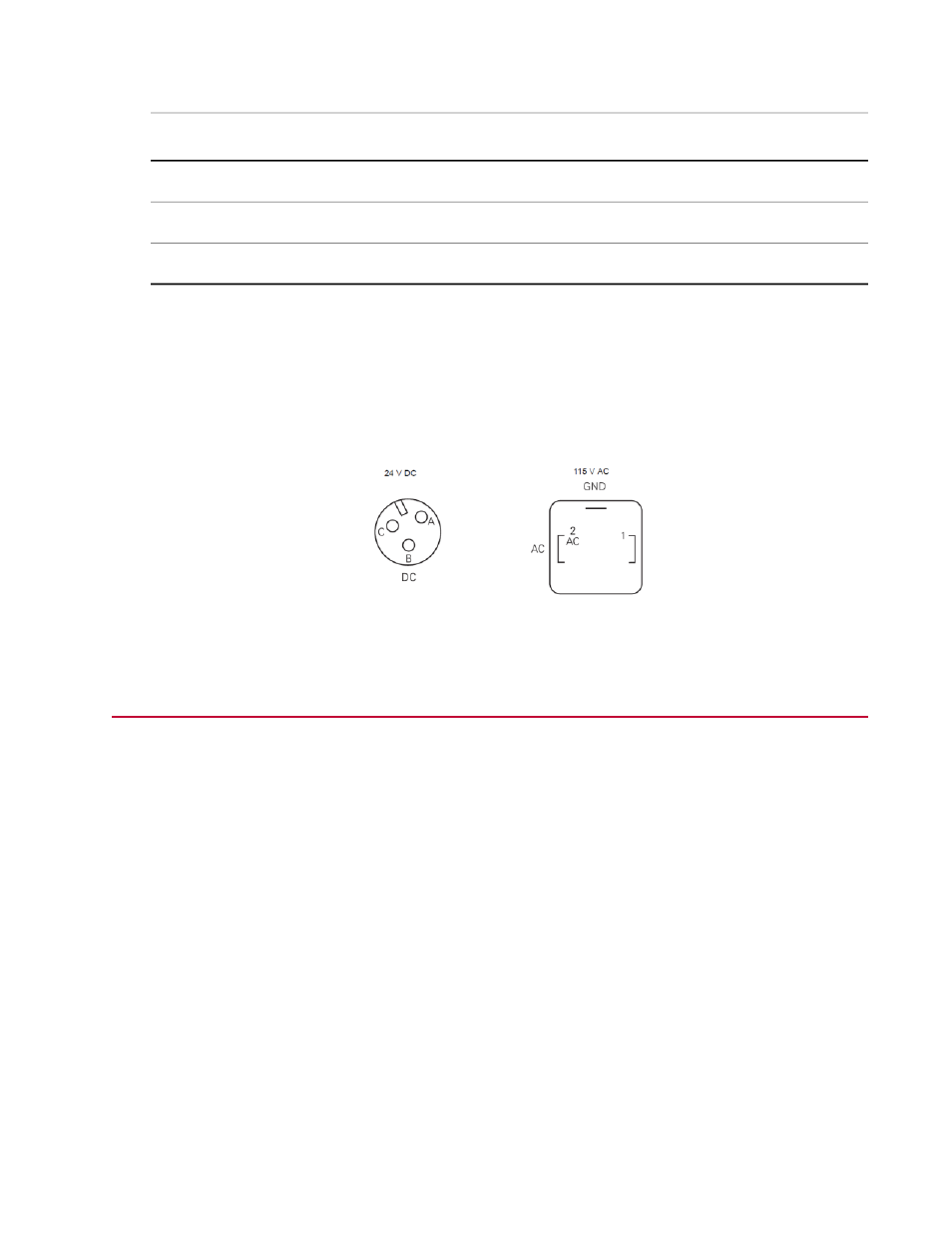
Depending on the model, the high/low solenoids may be powered by either 115 VAC or 24 VDC. The
following figure shows the pin assignments of each connector.
•
The Model 293.32A contains 24 VDC control power. The 3-pin connector for the high/low solenoids is
shown below.
•
The Model 293.32B contains 115 VAC control power. The 3-pin DIN connector for the high/low solenoids
is shown below.
Pin Assignments for High/Low Solenoid Connectors
System Checks
Complete the following steps to ensure proper HSM installation.
1. Check the HSM for secure mounting.
2. Check all hydraulic connections according to the system diagrams. Ensure that the connections are
secure.
3. Check all electrical cable connections (where applicable) according to the system diagrams. Ensure
that the connections are correctly mated and locked.
4. Precharge the accumulators. The procedure for precharging accumulators manufactured by MTS
Systems Corporation can be found in the Series 111 Accumulator Product Information manual. For
accumulators not manufactured by MTS Systems Corporation, refer to the vendor literature for that
accumulator.
5. Check to see if you have installed a shut-off valve and lock-out tag on each HSM to ensure that HPU
pressure is not applied to an HSM being serviced. Remember that pilot pressure is present whenever
there is supply pressure even if the HSM is off.
6. Apply low pressure. Check for leaks at all hose connections and on the HSM. With pressure turned off,
tighten fittings as necessary. Apply high pressure and check again for leaks.
7. Apply high pressure and operate the system for at least ten minutes to bleed air from the system.
Model 293.32 Hydraulic Service Manifold | 39
Installation