MTS Model 293-32 Hydraulic Service Manifold User Manual
Page 18
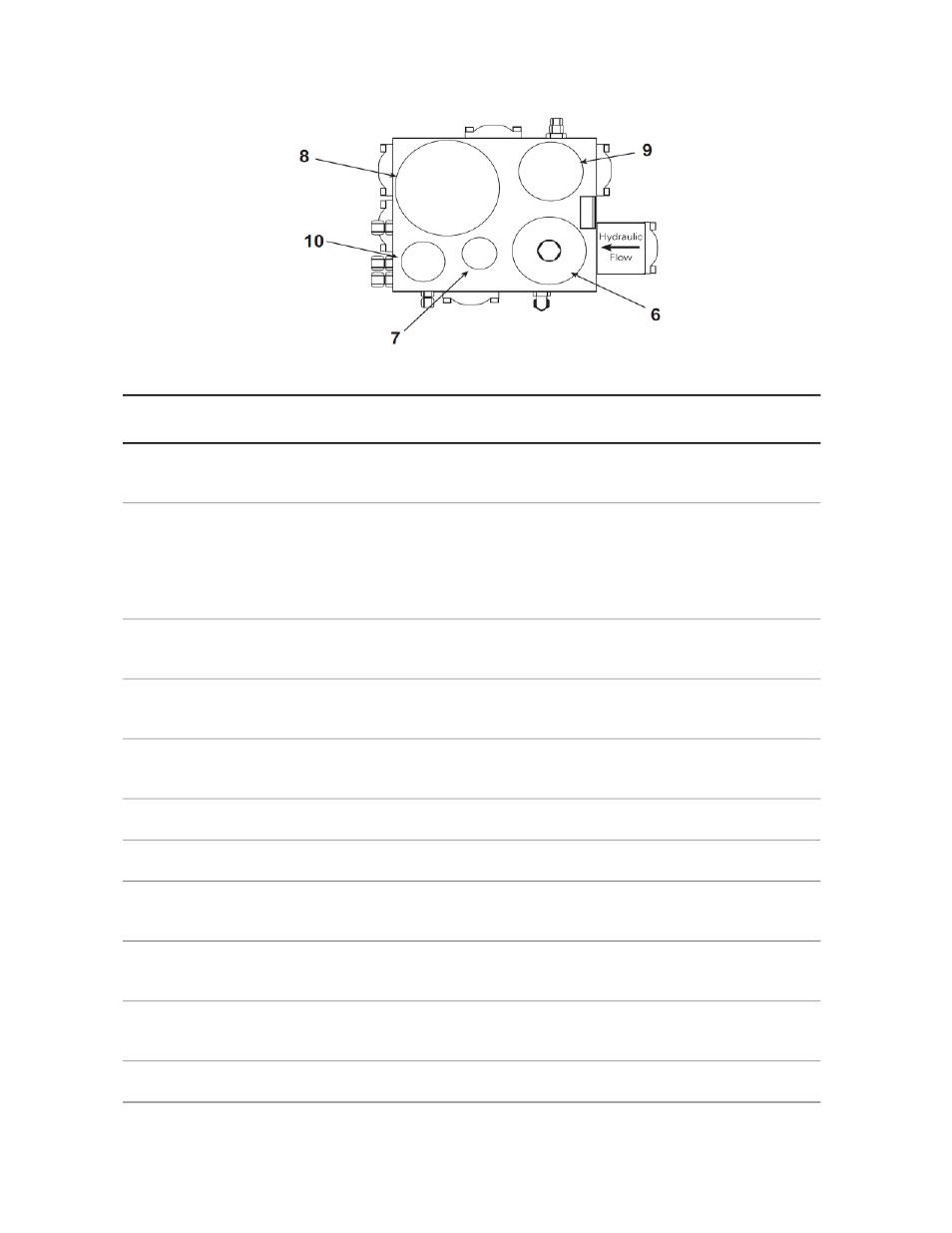
Top View
Description
Component
Distributes hydraulic fluid between the HPU and the control manifold.
It also has fittings for accumulators and filters.
Main manifold
1
Distributes hydraulic fluid to and from a single hydraulic channel. A
hydraulic channel is usually associated with an actuator and a
Control manifold
2
servovalve. The control manifold also contains a low-pressure solenoid
valve, a high-pressure solenoid valve, a main valve, a slow turn-on
valve, and a pressure gage.
Sets the low-pressure output of the hydraulic channel.
Low-pressure
adjustment
3
Allows low-pressure hydraulic fluid to be output to the hydraulic
channel.
Low-pressure solenoid
valve
4
Allows high-pressure hydraulic fluid to be output to the hydraulic
channel.
High-pressure solenoid
valve
5
Filters the hydraulic fluid as it is input to the main manifold.
Main filter
6
Filters the hydraulic fluid as it is input to the pilot pressure circuit.
Pilot pressure filter
7
Reduces pressure and flow fluctuations resulting from changing system
demands.
Pressure accumulator
8
Reduces pressure and flow fluctuations resulting from changing system
demands.
Return accumulator
9
Reduces pressure and flow fluctuations at the pilot pressure port.
Pilot pressure
accumulator
10
Indicates system hydraulic pressure.
Pressure gage
11
18 | Model 293.32 Hydraulic Service Manifold
Introduction