07/.11 hpu hydraulic schematic, 07/.11 hpu hydraulic schematic 17 – MTS Series 505 SilentFlo Hydraulic Power Unit Model 505-11 User Manual
Page 17
505.07/.11 HPU Hydraulic Schematic
Model 505.07/.11 SilentFlo™ HPU
Introduction
17
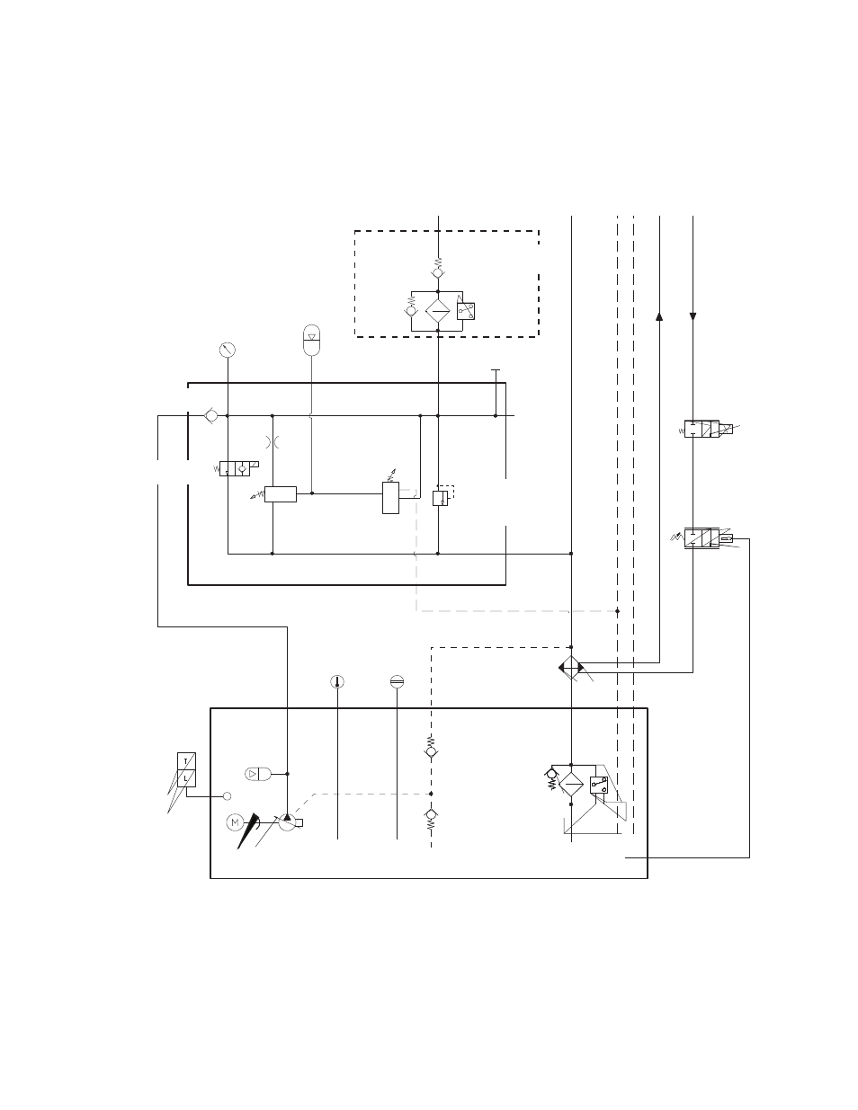
505.07/.11 HPU Hydraulic Schematic
The hydraulic schematic shows the functional layout of the Series 505 Hydraulic
Power Unit.
P
R
D D
W
W
Water
Shutoff
Valve
Water
Regulator
Valve
Heat
Exchanger
Sight
Gage
Temperature
Gage
Pump Drain
Check Valve
0.007 MPa (1.0 psi)
Pump Drain
Check Valve
0.034 MPa (5.0 psi)
3 Micron
Filter
Reservoir
Pump
Motor
Surge
Suppressor
(optional)
Temperature
and Low Level
Sensor
Control Manifold
Pressure
Gage
Oil Sample
Port
Optional
Pressure
Port
Pressure
Filter
(optional)
Auto-cooling
Valve
(adjustable)
Check
Valve
Pressure
Relief Valve
(factory set at
22.4 MPa (3250 psi)
High Pressure
Solenoid Valve
Auto-cooling
Valve
(factory set)
Accumulator
0.06 inch Orifice
0.007 MPa (1.0 psi)
This manual is related to the following products: