Magna-loc – Metal Sales Magna-Loc 180 User Manual
Page 12
PML-12
MAGNA-LOC
© Metal Sales Manufacturing Corporation/ Subject to change without notice/ Effective Date 9/11
800.406.7387 (Corporate Office) • www.metalsales.us.com
s
eCTion
P
roPerTies
& g
eneral
i
nforMaTion
Magna-Loc
Slope
Substructure
Clips
Coverage
Length
Fasteners
Availability
GENERAL INFORMATION
Base
Base
Clip
Clip
1
1
/
8
"
Clip
Magna-Loc
Panel
Factory Applied
Sealant
Factory Applied
Sealant
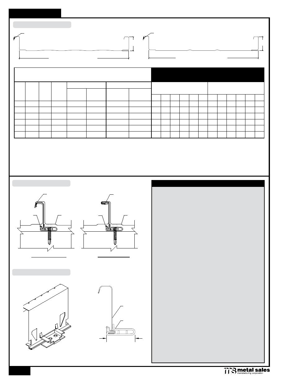
ATTACHMENT DETAILS
PANEL CLIP
The minimum recommended slope for the Magna-Loc
roof panel is 1/2:12.
Magna-Loc is designed to be utilized over open structural
framing or a solid substrate.
Clip spacing is based upon the spacing of structural
framing members and loading requirements.
Magna-Loc panels are available in a 2" seam height with
a 16" or 18" width coverage.
Minimum factory cut length is 5'-0" (with striations), 7'-0"
(without striations). Maximum recommended panel
length is 45'-0". Longer panels require additional
consideration in packaging, shipping, and erection.
Please consult Metal Sales for recommendations.
The fastener selection guide should be consulted for
choosing the proper fastener for specific applications.
Quantity and type of fastener must meet necessary
loading and code requirements.
NOTE: All panels are subject to surface distortion due to
improperly applied fasteners. Overdriven fasteners will
cause stress and induce oil canning across the face of
the panel at or near the point of attachment.
Finishes: Acrylic Coated Galvalume
®
and
PVDF (Kynar 500).
Gauges: 24 ga standard, 22 ga and 20 ga optional
BEFORE SEAMING
AFTER SEAMING
Clip
Magna-Loc
Panel
1. Theoretical section properties have been calculated per AISI 2001 “Specification for the Design of Cold-formed Steel Structural Members.” Ixx and Sxx are
effective section properties for deflection and bending.
2. Allowable load is calculated in accordance with AISI 2001 specifications considering bending, shear, combined bending and shear, deflection, and ASTM 1592
testing for 24 ga and 22 ga. Allowable load considers the worst case of 3 and 4 equal span conditions. Allowable load does not address web crippling or
fasteners/support connection or testing for 20 ga and panel weight is not considered.
3. Deflection consideration is limited by a maximum deflection ratio of L/180 of span.
4. Allowable loads do not include a 1/3 stress increase in uplift.
SECTION PROPERTIES
ALLOWABLE UNIFORM LOADS psf
(3 or More Equal Spans)
Ga. Width
in
Yield
ksi
Weight
psf
Top In Compression Bottom In Compression
Inward
Load
Outward
Load
Ixx
in
4
/ft
Sxx
in
3
/ft
Ixx
in
4
/ft
Sxx
in
3
/ft
2.5' 3' 3.5' 4' 4.5' 5' 2.5' 3' 3.5' 4' 4.5' 5'
24
16"
50
1.25
0.1785
0.1013
0.0855
0.0754
161 126 101 82 68 57 111 99 87 75 63 51
22
16"
50
1.63
0.2468
0.1419
0.1178
0.1066
257 197 155 125 103 86 119 110 101 92 83 74
20
16"
33
2.02
0.3165
0.1831
0.1643
0.1474
252 189 147 117 93 76 392 283 213 166 133 109
24
18"
50
1.21
0.1620
0.0900
0.0760
0.0669
144 112 89 73 61 51
68 62 56 50 43 37
22
18"
50
1.58
0.2233
0.1255
0.1047
0.0947
233 176 138 111 91 74
78 73 68 62 57 52
20
18"
33
1.96
0.2893
0.1640
0.1460
0.1310
224 168 131 104 83 67 350 253 191 149 119 97
Factory Applied Sealant
Striated
2"
16" or 18" Coverage
Factory Applied Sealant
2"
16" or 18" Coverage
Pencil Ribs