Optional drain pump installation – MARVEL Scientific 6ADi User Manual
Page 7
30CM Installation
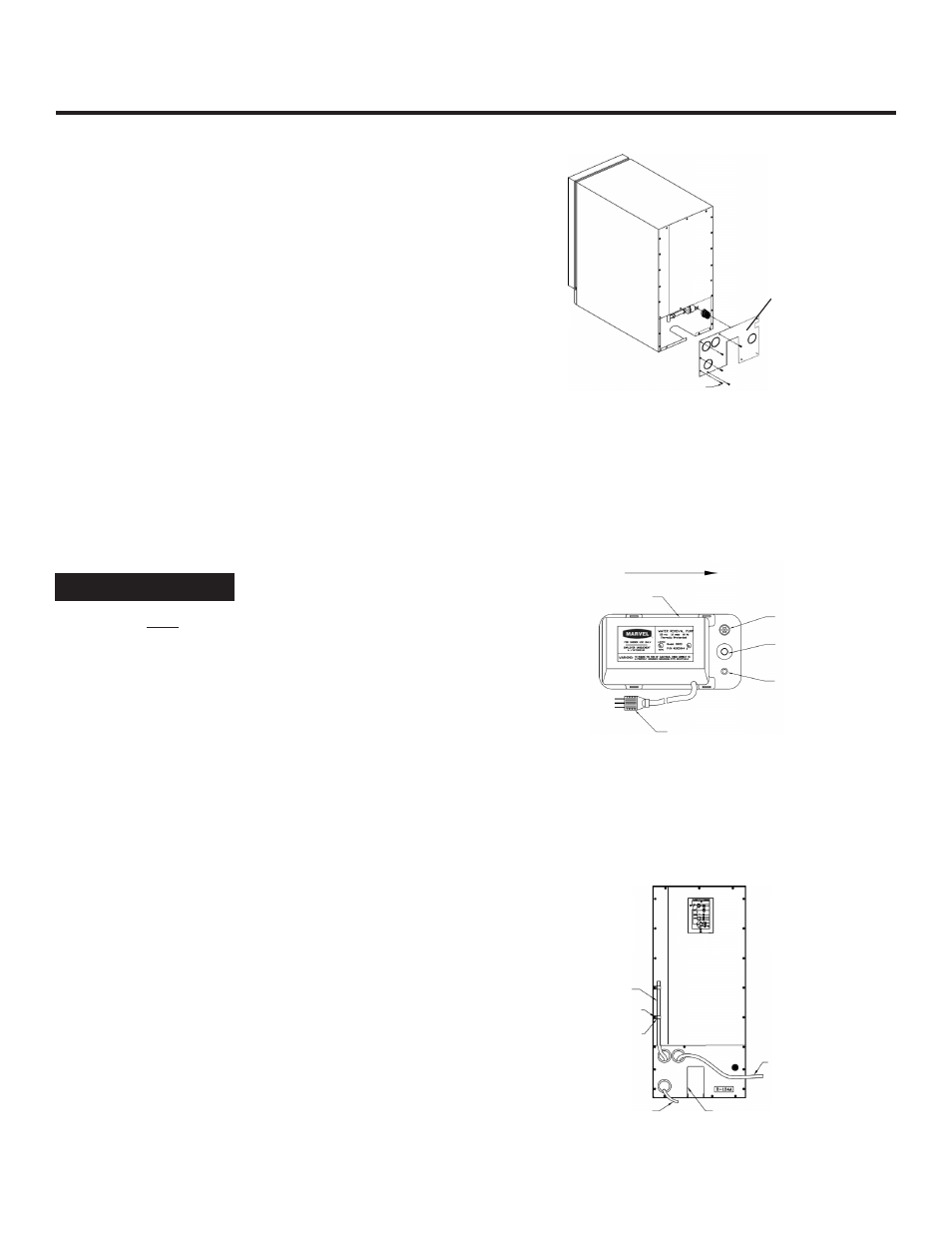
1. Turn the ice machine to gain access to the rear of the unit.
Remove the access panel by removing the ten (10) screws
(see Figure 7).
2. Plug the ice machine’s power plug into the outlet on the
drain pump. Place the drain pump in the left, rear opening
of the ice machine with the inlet, vent, and discharge fittings
to the rear of the unit (see Figure 8).
3. Install 1-3/4 in. x 5/8 in. I.D. inlet tubing to drain barb on ice
machine and then on the inlet of the drain pump. Clamp
both ends of the tube with the large tubing clamps.
4. Connect the 18 in. x 3/8 in. I.D. formed vent tube to the vent
on the drain pump and secure with one (1) of the small tub-
ing clamps.
5. Route a short section of the 20 ft. x 3/8 in. I.D. tube through
the opening in the access panel and connect it to the
discharge of the drain pump. Secure with the small tubing
clamp.
6. Route the vent tube and the drain pump power cord
through the remaining openings in the access panel as
shown in Figure 9. Reinstall the panel and secure.
7. Secure the vent tube to the back of the ice machine using
the supplied tubing clips and screws as shown in Figure 9.
The vent tube must be attached and secured or water damage
may occur. Make certain there are no kinks in the tube. The
drain pump will not operate correctly with a partially blocked
vent line.
8. Connect the discharge tube to a suitable drain. Cut excess
tubing as needed. Do NOT allow sags or kinks in the tubing
that will restrict flow.
9. Make certain that the drain pump is level in the ice ma-
chine’s rear opening.
10. Plug the power cord of the drain pump into a properly
grounded 115VAC receptacle.
11. Test the drain pump by slowly pouring water into the ice ma-
chine ice storage bin. Approximately one (1) quart of water
is required to activate the drain pump.
12. Test the operation of the safety switch by turning the ice
machine on and completely restricting the discharge line
while the pump is operating. Pour more water into the ice
machine’s ice storage bin until the ice machine turns off.
The drain pump will continue to operate. Remove the dis-
charge tube restriction and allow the water to be pumped
out. The power to the ice machine will be restored when
the water in the pump returns to normal.
13. Place the ice machine in the installed location. Ensure
that all tubing and power cords are not pinched, kinked, or
disturbed.
Figure 7
Figure 8
Receptacle for Ice
Machine’s Plug
Towards the Rear of
the Ice Machine
To Wall Receptacle
Inlet Tube
Fitting
Discharge
Tube Fitting
Vent Tube
Fitting
Access Panel
Figure 9
Vent Tube
Drain Pump’s
Power Cord
Access Panel
Screws
Tubing Clips
To Drain
OPTIONAL DRAIN PUMP INSTALLATION
NOTE
Screws
7