Water separator diagram and assembly to unit – Longevity WeldAll 160PI/200PI/250PI User Manual
Page 18
160PI/200PI/250PI AC/DC Series IGBT Machines
www.longevity-inc.com
17
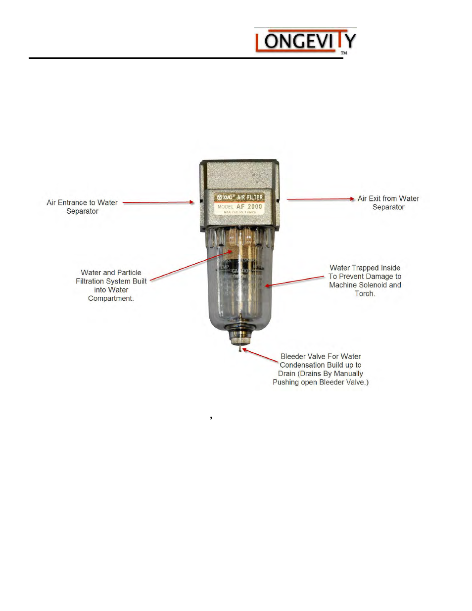
Water Separator Diagram and Assembly to Unit:
LONGEVITY® includes an external water separator with your machine. You must attach the bracket to the
holes dedicated on the back of the machine and fasten the water separator to the bracket so that it mounts face
out as pictured.
1. Locate the ENTRANCE and OUTLET on the water separator labeled on the diagram pictured above and
attach the hose coming from the Air Compressor to the ENTRANCE side on Water Separator. Attach
the smaller clear plastic hose provided to the EXIT side of the water separator, leading into the back of
the machine. Secure both lines with quick connects given for assembly with water separator (Standard
quick connect used on inlet side). Set compressor above 75 PSI and set your Air regulator on the
front of the machine to 75 PSI exactly. Proper air pressure is key to cut quality and consumable
life.
2. Periodically, after long periods of use, you must remove water from the water separator by pushing the
bleeder valve inward to release water from the water separator section of the regulator.