Epm-h606 operating unit with 42-pole plug, Epm−h606 operating unit with 42−pole plug, Electrical installation – Lenze EPM−H606 User Manual
Page 75
Electrical installation
Assignment of connecting cable − overview
EPM−H606 operating unit with 42−pole plug
l
75
EDBPM−H605 DE/EN/FR 7.2
Abbreviation
Colour
Abbreviation
Colour
Abbreviation
Colour
BK
Black
BN
Brown
RD
Red
YE
Yellow
GN
Green
BU
Blue
VT
Violet
GY
Grey
WH
White
PK
Pink
GNYE
Green/Yellow
OG
Orange
5.1.2
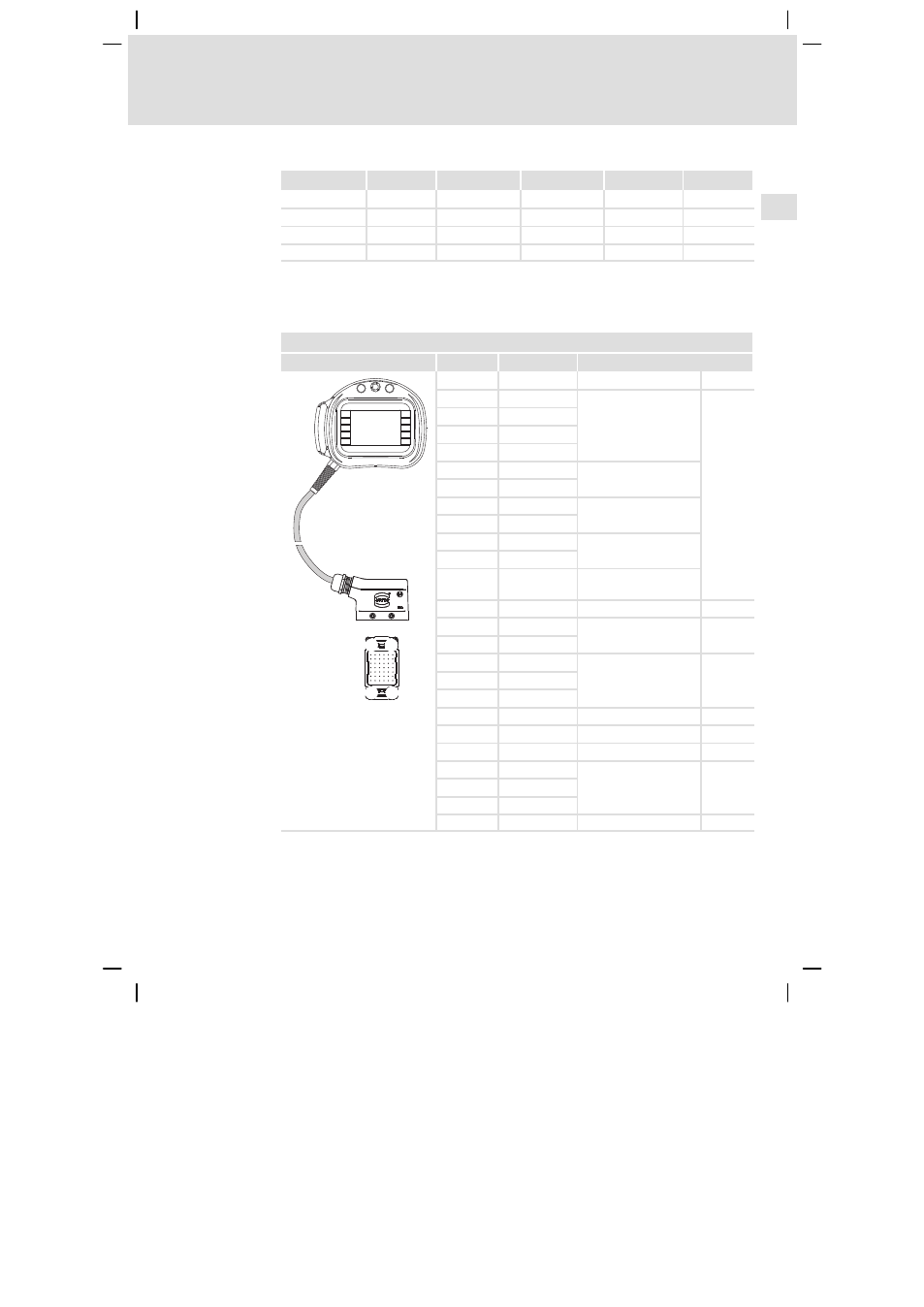
EPM−H606 operating unit with 42−pole plug
(operating unit with hardware versions 1A and 1B only)
Pin assignment of the connector plug of the EPM−H606 operating unit
Graphics
Pin
Signal
Description
F9
F7
F8
F4
F5
F2
F3
F1
F10
F6
1
7
36
42
1 ... 4
Not connected
5
C1
Confirmation key (rear
side of operating unit)
^
6
NC1
7
C2
8
NC2
9
Key, black
10
11
Illuminated key, white
12
13
Lamp, white
14
15
NO1
Confirmation key (rear
side of operating unit)
16 ... 20
Not connected
21
+24 VDC
Supply voltage
^
22
0 VDC
23
CAN−LOW
System bus (CAN)
^
24
CAN−HIGH
25
CAN−GND
26
Not connected
27
CAN shield
System bus (CAN)
28 ... 30
Not connected
31
Tx RS232
Transfer signals
^
32
Rx RS232
33
GND signal
34 ... 42
Not connected