Electrical installation, Assignment of connecting cable - overview, Epm-h605 operating unit – Lenze EPM−H606 User Manual
Page 74: Assignment of connecting cable − overview, Epm−h605 operating unit, 5electrical installation, Stop
Electrical installation
Assignment of connecting cable − overview
EPM−H605 operating unit
5
l
74
EDBPM−H605 DE/EN/FR 7.2
5
Electrical installation
(
Stop!
Wire operating unit in deenergised state only!
5.1
Assignment of connecting cable − overview
5.1.1
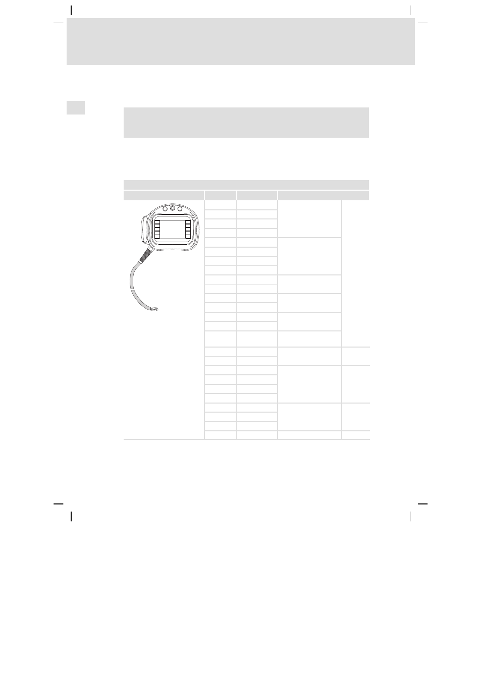
EPM−H605 operating unit
Core assignment of the EPM−H605 operating unit
Graphics
Core colour Signal
Description
F9
F7
F8
F4
F5
F2
F3
F1
F10
F6
WHBK
Stop key
PKBN
GYBN
WHBU
BNRD
C1
Confirmation key (rear
side of operating unit)
YEBN
NC1
VT
C2
BNGN
NC2
WHGN
Key, black
WHPK
GYPK
Illuminated key, white
RDBU
GY
Lamp, white
BN
BNBU
NO1
Confirmation key (rear
side of operating unit)
RD
+24 VDC
Supply voltage
BK
0 VDC
BU
CAN−LOW
System bus (CAN)
^
74
WHYE
CAN−HIGH
GN
CAN−GND
WHGY
CAN shield
PK
Tx RS232
Transfer signals
WH
Rx RS232
YE
GND signal
WHRD
Not connected
This manual is related to the following products: