Epm-h606 operating unit with 20-pole plug, Epm−h606 operating unit with 20−pole plug, Electrical installation – Lenze EPM−H606 User Manual
Page 76
Electrical installation
Assignment of connecting cable − overview
EPM−H606 operating unit with 20−pole plug
l
76
EDBPM−H605 DE/EN/FR 7.2
5.1.3
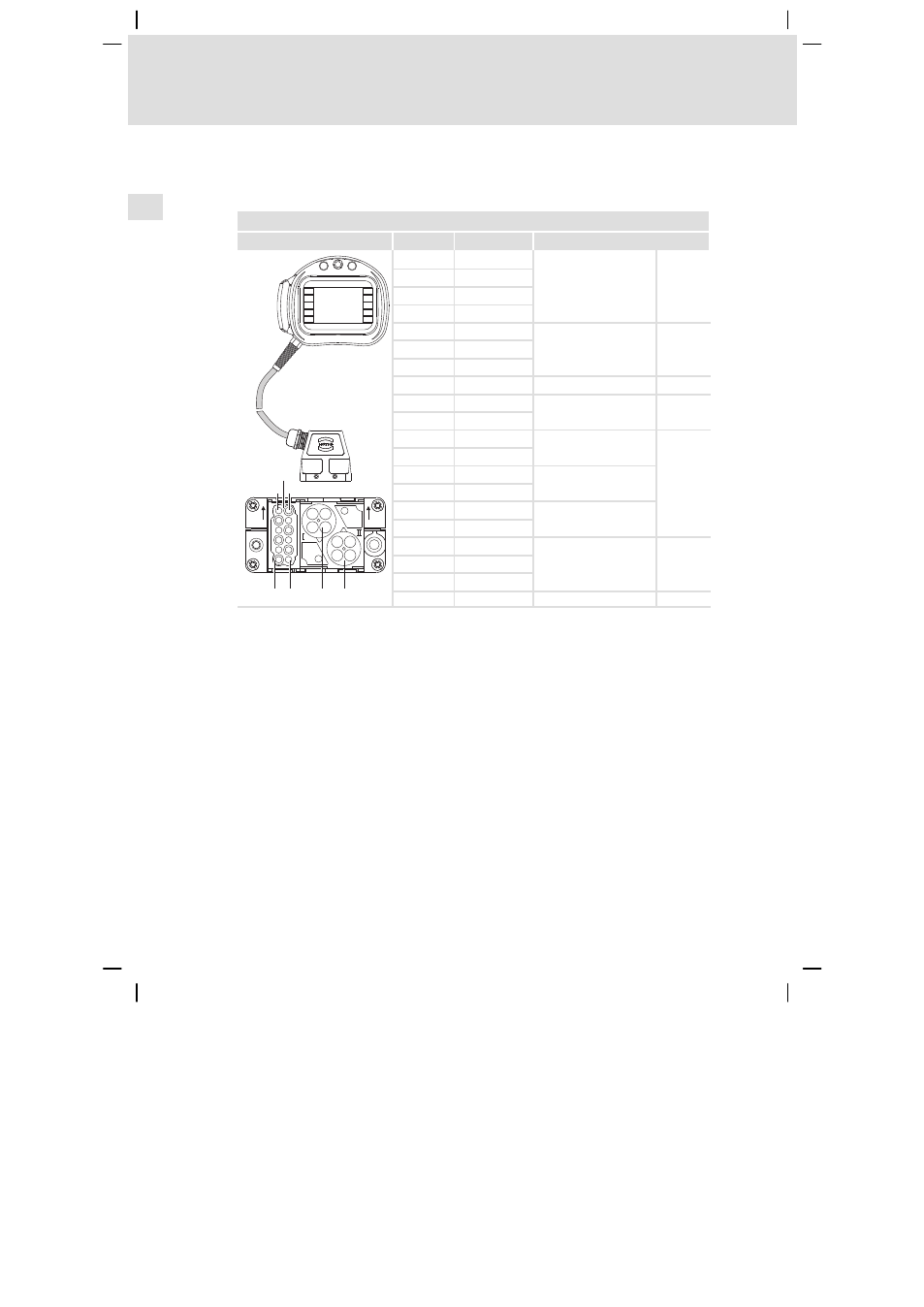
EPM−H606 operating unit with 20−pole plug
(operating unit with hardware version 1D only)
Pin assignment of the connector plug of the EPM−H606 operating unit
Graphics
Pin
Signal
Description
F9
F7
F8
F4
F5
F2
F3
F1
F10
F6
1
2
3
4
5
6
8
9
10
11
12
7
A
C
1
7
12
A
B
C
6
1 2
3
4
1
2
3 4
A1
C1
Confirmation key (rear
side of operating unit)
A2
NO1
A3
C2
A4
NO2
B1
CAN−HIGH
System bus (CAN)
B2
CAN−LOW
B3
CAN−GND
B4
Not connected
C1
+24 VDC
Supply voltage
C2
0 VDC
C3
Illuminated key, white
C4
C5
0 VDC
Lamp, white
C6
+24 VDC
C7
Key, black
C8
C9
Tx RS232
Transfer signals
C10
Rx RS232
C11
GND RS232
C12
Not connected
This manual is related to the following products: